Below we will briefly review adding operation Steps to the Unisoft
software and then introduce adding Substeps to those Steps. We assume
that you have a basic working knowledge of the Unisoft software. If
you have questions please contact us.
The Unisoft software can
add
Steps
to part numbers on the PCB you are working on to partition them into
different assembly operations, inspection operations, etc.
These component part
numbers in their Steps can then be assigned unique colors, instructions and
more. Then process documents, kitting labels., etc. can be created.
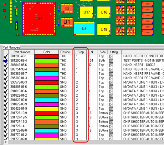
When the PC Board and BOM are first imported into the Unisoft
software all Step numbers are defaulted to Step 1.
In the
figure above at the bottom of the software display is the Smart Color window and to the right of
the PART NUMBER field you will find the STEP field. In this field you may
optionally add STEP NUMBERS to part numbers in order to create separate
unique steps in the PC Boards assembly process (for example: Step 1 for Hand
Inserts, Step 2 for Mydata/Mycronic assembly machine placements, Step 3 Chip
Shooter component placement, etc.).
To assign a STEP NUMBER to a part number
at the bottom of the display double click on a part number and edit the STEP
field with a step number.
SUBSTEPS: These
Steps can further be broken down into Substeps. We will review the Substep process
below.
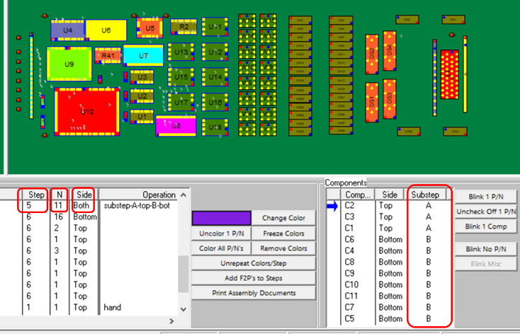
In the above figure we have an example of a Substep
that was added. In this case the Step number is 5 and there are 11
components for this part number in this step and those 11 components are
located on both sides of the PCB. In the right hand side of the figure
we created Substeps A and B for this Step #5. Now Substep 5A
includes the 3 components on the top side of the PCB and Substep 5B includes
the 8 components on the bottom side. As a result the assembly
documents, inspection documents. etc. created will be separated into two
separate Substeps and used accordingly as required as part of the
manufacturing of the finished assembly process.
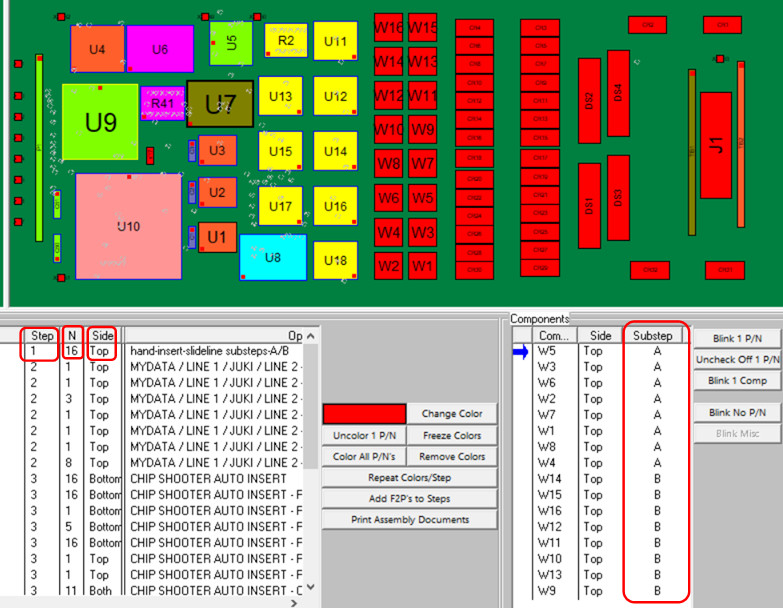
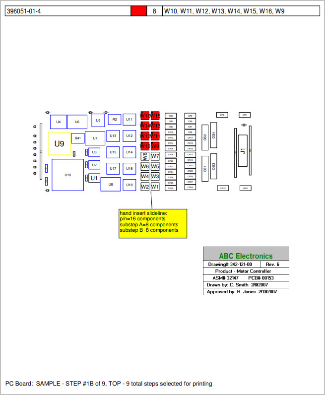
In the figure above is another example of a use for
Substep. For instance, if the PCB was being assembled in a slide line and
one of the part numbers being assembled had a large quantity of components
and you wanted to distribute that among the slide line assemblers then you
could use Substep to assign a certain number of components to each
assembler.
In the above figure in this case the Step number is
1 and there are 16 components for this part number in this step and those 16
components are all located on the top side of the PCB. In the right
hand side of the figure we created Substeps A and B for this Step #1.
Now Substep 5A includes 8 components of the 16 components and Substep 5B
includes the balance of the remaining 8 components. As a result the
assembly documents, inspection documents. etc. created will be separated
into two separate Substeps and used accordingly as required as part of the
manufacturing of the finished assembly process.
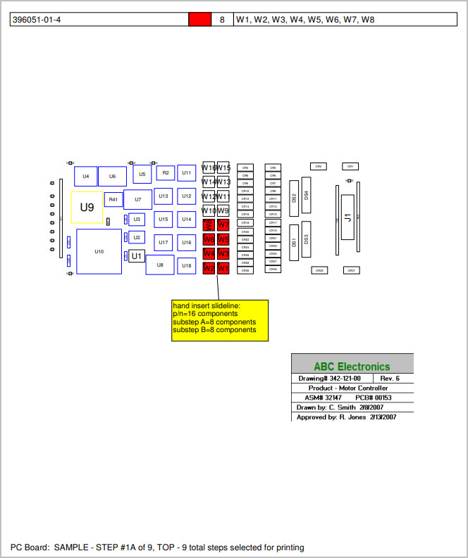
The 2 figures below
are the resultant assembly documents created for Substeps 5A and 5B.
The first figure below, Substep 5A, includes 8 components of the 16 components and
the second figure, Substep 5B, includes the balance of the remaining 8
components.
I
If a
Step has multiple part numbers and a Substep is assigned with the same
letter A through E for different part numbers within the Step then those
components using that same Substep will be join together within that
Substep.
Related information:
Assembly documents -
sample of how to create assembly documents
Assembly documents - adding steps to part numbers
Assembly documents -
manual "tutorial 1 - creating assembly/process sheets, annotation overlays and kitting labels"
Assembly
documents - printing assembly documents
Assembly documents -
kitting labels-1
kitting labels-2
kitting labels-3
Assembly documents - single page per step.
Assembly documents - multiple pages per step
Assembly documents -
powerpoint and custom types
Assembly
documents - editing multiple assembly steps
Assembly documents - add pcb photos, etc. to the display background
Assembly documents -
for paperless assembly instructions when using the display only for slide
line pcb assembly, etc.
Barcodes on the display and assembly
documents