
To start or schedule a meeting
Click Here or email us (enable JavaScript for our email addresscad-to-cad.php) or call us (enable JavaScript for our phone number).
In our meeting, we can follow any direction you prefer, for instance:
-- Talk about your requirements, software inquiries, and other concerns.
-- Software demonstrations & training. We have the option to process one of your PC Boards or demonstrate the software using our own data files.
-- Provide you with a fully functional trial version of the software license.
-- etc.
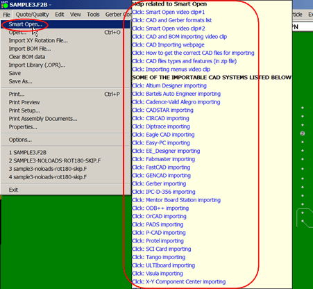
Trial Software (The trial software you can use at no cost. Start using the fully licensed software for as little as $500. For over 35 years, Unisoft has had the best prices.) - Another quick way to learn about the software is to download the Trial Software (The trial software you can use at no cost. Start using the fully licensed software for as little as $500. For over 35 years, Unisoft has had the best prices.).
The trial software has HELP for most menu items by hovering over the menu item for a second then click any of the videos, manual or website links to learn about the software.

Use our in-house ATE TESTER AND FIXTURE TRANSLATION SERVICES to convert your CAD or GERBER files into real reference designators, netlists, X/Y component pin geometries, values, tolerances, part numbers, etc. Also Gerber to Takaya Flying Probe IPC-D-356 / IPC-2581 / ipc2581 file. This data is then used by Test Engineers to program their ATE (Genrad ".ckt", Teradyne "ipl", Hewlett Packard "board & board x/y"), MDA, and flying probe test equipment (Takaya, Spea, etc.) and design the "Bed of Nails" test fixtures. Need gerber conversion, gerber to netlist, x/y, etc.? Some projects require multiple PCB's, restrictions may apply. Contact Unisoft for details or fill in the "ASSEMBLY EQUIPMENT PROGRAMMING SERVICE FORM" below.
Do you have special problems such as gerber translation? For example: You do not have the native CAD files for your project. You only have the raw Gerber Files and a BOM (Bill Of Materials). You need to program your ATE "Automatic Test Equipment" and you do not know where to turn then our software can do it for you. It can take your gerber files and BOM and create the exact Reference Designators, Net List, X/Y, Part Number, Values and Tolerance data you need to program your project. Of course the software also imports virtually all standard native CAD file types too!
You may already have Test software that you use to program your ATE Test equipment but you need a way to convert newer or non supported cad file formats to this software. Unisoft can import virtually any CAD format and export a standard file for import to your existing ATE Test software. Output formats include GENCAD, Fabmaster, ipcd356, ipc-2581, ipc2581, Mentor Graphics, PADS .ASC, etc. For example, Unisoft can import virtually any CAD file format and export to Teradyne/Genrad D2B Alchemist or Fabmaster Test Expert software. We can sell you this software for your use or can perform a translation service for you and return the correct files to you. Some restrictions may apply.
If you are at that point a possible next step in your evaluation is an online demonstration. For questions or to schedule a demonstration, call us (enable JavaScript for our phone number) or email us (enable JavaScript for our email address).
IMPORTING CAD FILES: A list and samples of the CAD file formats Unisoft imports are on our Importing CAD Files page.
Sample test equipment and fixture setup files created by Unisoft ProntoTEST-FIXTURE (all popular machine specific formats supported):
AGILENT/HEWLETT PACKARD HP307X OUTPUT — BOARD & BOARD X/Y FILES:
*Dig U1 386EX P/N 395380-01-4;
*Cap C1 10u 20 20 f P/N 3H100M-CR-1;
*Ind L1 33u 10 10 10 f P/N 3XCTX3-32-P;
*Res R12 10k 1 1 f P/N 3XBT10-02-F;
*Devices
BATT1 1.UN002137 2.GND 5.UN002137 6.GND;
C1 1.+5VB 2.GND;
*XY
C6 1 X 2.200 Y 2.750
C6 2 X 2.200 Y 2.850
GENRAD OUTPUT:
%CIRCUIT;
GND EXT ,N1;
VCC EXT ,N35;
C1 C 1=N1, 2=N1;
C10 C 1=N9, 2=N1;
D1 CR A=N163, C=N138;C1 C 1=N1, 2=N1;
%VALUE:12345;
C1 = .022U, +20%, -20%, MSG='S13-217 PL#1 ';
CR3 = 800M, +5%, -5%, MSG='S13S-45 PL#77 ';
%ADAPTER:2282:TEMP;
H1=N1; /* 1 U2-3 H 84/ 114 SMD */
H2=N2; /* 2 U5-14 H ** All 3 Pins SMD */
TERADYNE OUTPUT:
INPUTLIST, C:PCB.IPL
SH,0,1,16-1999
R,R1,"RES,P1,150k,5%",150k,5%,0,0C,C8,"CAP,C8,.1UF,20%",.1UF,20%,20%,22,0
C,C9,"CAP,C9,47UF,20%",47UF,20%,20%,22,0
D,CR3,"",0,173
D,D1,"DIODE",176,151
IC,U14,"P/N 74HCT74",74HCT74,95,96,97,98,85,84,83,82,81,92,93,99,100,101,102,103
TEST FIXTURE FABRICATION FILE:
\* Probe Spacing: 100 mils *\
P2 1 X 3.300 Y 0.300
P2 2 X 3.200 Y 0.200
P2 3 X 3.100 Y 0.300 238 - 2402
P2 4 X 3.000 Y 0.300 312 - 0502
CR2 1 X 5.275 Y 5.950
CR2 2 X 5.375 Y 5.950 378 - 1805
\* Probe Spacing: 75 mils *\
GP1 1 X 4.940 Y 5.610
GP4 1 X 2.475 Y 5.250
J1 1 X 0.700 Y 5.425 148 - 0104
J1 2 X 0.700 Y 5.504 123 - 2506
J1 3 X 0.779 Y 5.425 147 - 0005
J1 4 X 0.779 Y 5.504 122 - 0004
IPC-D-356 OUTPUT:
327GND D21 -2 A02X-063625Y+017450X0000Y0000
327GND D23 -2 A02X-060625Y+020950X0000Y0000
327GND D25 -2 A02X-063625Y+020950X0000Y0000
317GND J1 -5 D0670PA00X+000000Y+004510
317GND J10 -4 D0400PA00X-075000Y+003000
GENERIC OUTPUT has every component pin. Can be used to setup various test equipment:
54 - VCC C1.1 X -4.800 Y 0.320 Top Smd
149 - GND C1.2 X -4.800 Y 0.180 Top   Smd
54 - VCC C10.1 X -5.125 Y 0.720 Bottom Smd
149 - GND C10.2 X -5.125 Y 0.580 Bottom Smd
As a bonus the conversion is compatible with our ProntoVIEW-MARKUP software and all other Unisoft OneFACTORY modules. With VIEW-MARKUP you can display the PC Board assembly and actively search test probes by number, components, pins, etc. Click here for more VIEW-MARKUP information.

Customer Comments
Jim Wasilewski
MPI
Bill Schulte
Paragon Software, Inc.