Skip navigation
For over 40 years, Intelligent PCB Manufacturing
Automation Software
Be production ready in minutes, not days.

Sometimes the fiducial line-up data required for a PCB project is in the gerber file.
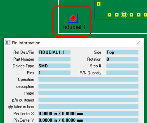
Note if a gerber point displays as Orphan Pin or ?00000 then it is
still raw gerber data and the Make Component
feature needs to be used in order to use it as a Mark Reference 1, 2, etc.
point. The other option is to use the Make Point
feature to turn those same XY positions into fiducials and to do this the
Make Point feature is placed exactly over
those gerber points and then new points are created that can then be used as the
Mark Reference 1, 2, etc. points.
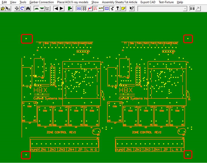
For example, in the figure below
of the gerber data file the fiducials that are needed to be
used are outline in red.

The Add Layer feature on the Gerber Connection menu allows you to
overlay a gerber layer to an existing CAD file, gerber file or X Y Rotation
file that is being displayed and this gerber layer maybe the only source of the
fiducial line-up points that are on the PCB.
If needed the gerber data added can be lined up to the data already displayed on the screen.
Next the Make Component or the Make Point feature can be used to turn the desired points into fiducials.
Then those points can be set to the reference points.
Also one of those points can be set to origin X Y 0,0 if desired.
Contact Unisoft if training is needed for this process.