Full CAD files are the best choice when working your project in the Unisoft software. However when full CAD files are not available and there is no other choice but to use Gerber file data then this gerber file data can usually be process relatively quickly with the Unisoft software. The Unisoft software has a feature that takes the Flashed Gerber Pad pins and converts them to real components and pins, for example U14 pins 1,2,3, etc.
However a small percentage of the time these gerber files may have additional issues where some or all of the component pins in the Gerber files are not Flashed Pads. Sometimes this is the case in older legacy design PC Boards where the CAD designer who designed the PCB assembly ( PCBA ) may have not created a typical model for the components and the component pins for those components will be displayed as line draws instead of pad flashes. This can also be the case in newer design PCB's but not as often. The Unisoft software can convert these line draws into pad flashes and below is some information on that process.
In the gerber data file when the situation is that the pins a the copper pads are not Flash Pads as they should be but instead are just a single short line or a number of lines forming a rectangular shape pads representing the component pins, then the Unisoft software can usually remedy this situation by converting these pads from lines to solid pads/flash pads using the SHORT DRAW to FLASH conversion feature.
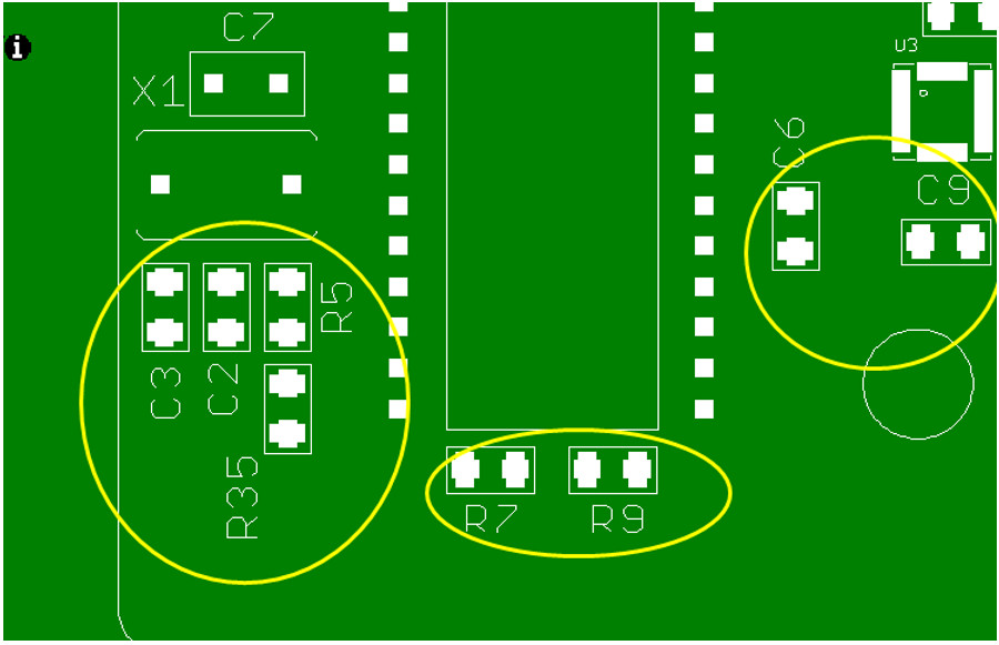
Examples of these incorrect pins are outlined in yellow in the figures below and the correctly flashed pads are outlined in red.

Normally the reason for an incorrect pad/pin condition is the CAD System / CAD Designer did not model those components in the CAD system as is the normal process. So because of this those components on the PCB assembly ( PCBA ) don't have Flashed Pads instead they have silkscreen Short Draws to represent the component pins. Another words the pins are for the most part no different than any other silkscreen on the board for example silkscreen that indicates lettering or board outline or any other figure.
Usually all components shapes are modeled in the CAD system and therefore when generated on the PCB assembly ( PCBA ) the pins on the components are the correctly Flashed Pins. However if components are not modeled as normal this maybe because they are either older legacy PCB assembly ( PCBA ) designs or from less sophisticated CAD systems or sometimes novice CAD designers.
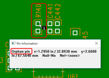
One way to tell if the pad/pin this correctly flashed is to click the pin with the INFO tool and a correctly Flashed Pad will display as an ORPHAN PIN.
The Unisoft software can convert these line draws into pad flashes and below is some information on that process.
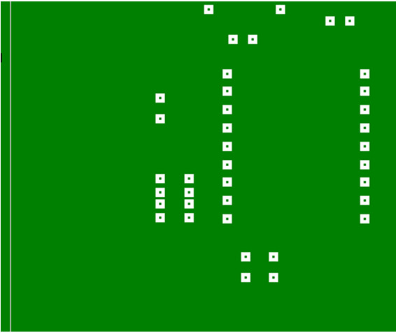
When you view most Gerber files the component pins will be displayed as pad flashes which usually look like a solid square or rectangle, as in the figure below, and these are normally how they should be displayed.
If on looking at the Gerber files it may look like some or all of the components are not pad flashes but that they were simply drawn basically with line draws (example circled in yellow below). Note that these line draws can also be seen as short straight lines.
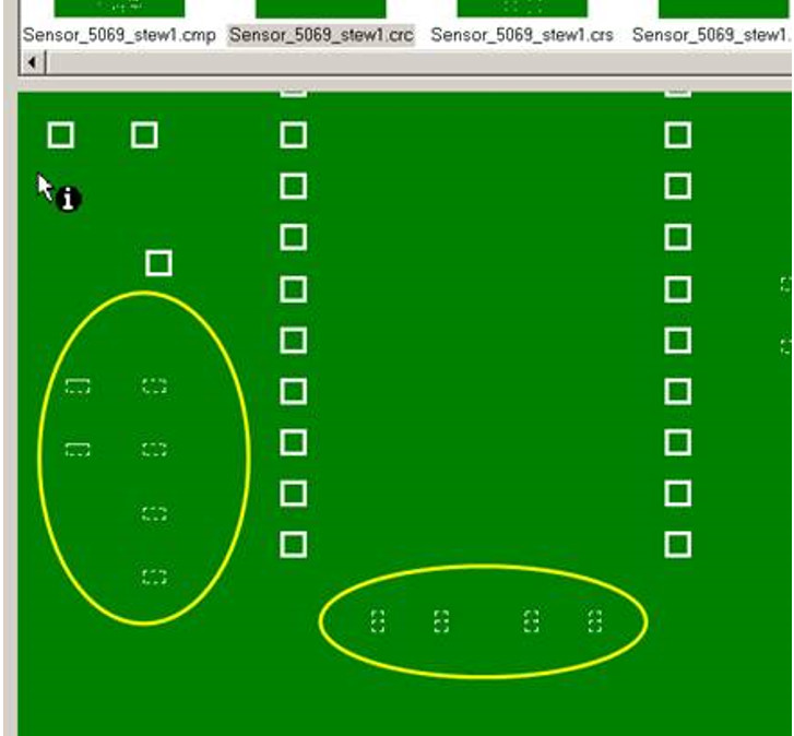
To utilize this Gerber data properly these pins need to be converted to Pad Flashes. So to get around this problem basically you can use the Unisoft short draw feature on that particular layer only and it will turn the short draws into pad flashes (circled in yellow below).
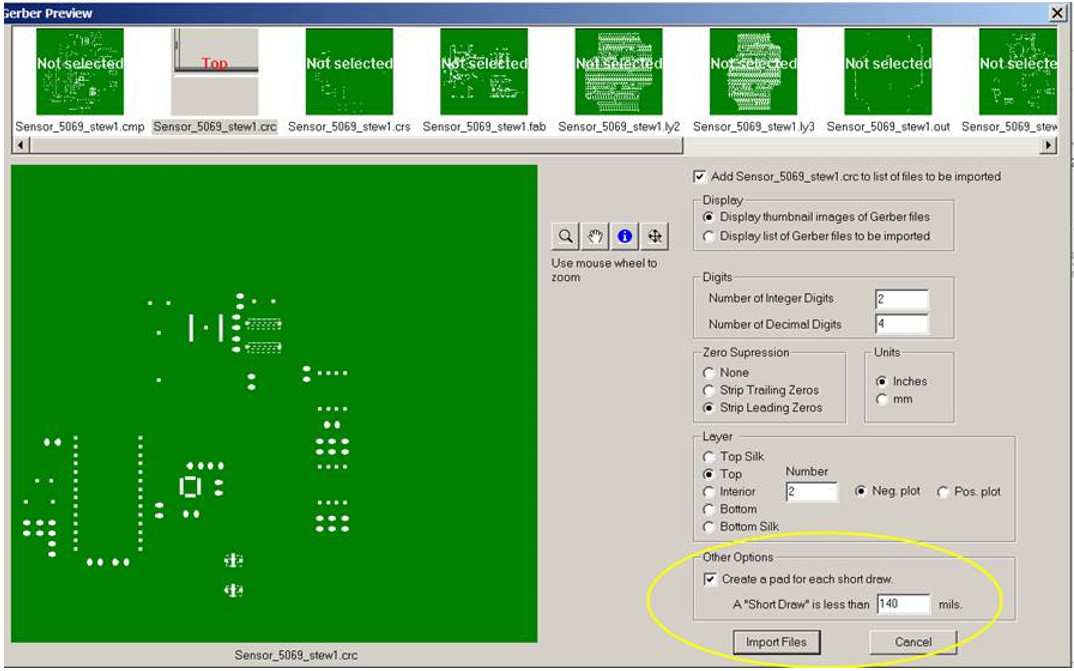
The result is it ends up creating pad flashes in those areas so you can then MAKE those pad flashes into components and pins using the Unisoft software. At that point the Unisoft software can calculate the X/Y center for those components then you can use that data to program your assembly or AOI machines. Also the displayed components can be used to create process assembly documentation, etc.
Please contact Unisoft for training or any questions on this feature.