- Software Products
- Trial Software
- CAD Translation
- Testimonials
- Overview
- Pricing
- Knowledge Base
- Contact Us -
- Languages
When designing a PCB assembly ( PCBA ) CAD systems standardly lay out the components on the top and the bottom of the PCB assembly ( PCBA ) relative to the top side of the PCB. Also the top side components are normally rotated in the counter clockwise (CCW) direction when viewed from the top of the PCB. So since the bottom side rotations are relative (tied to) the top then the bottom side component rotations are rotated clockwise (CW) when the PCB assembly ( PCBA ) is viewed from the bottom.
Although there has been progress in recent years there is not a global standard for zero degrees rotation of components. Possibly the most agreed upon rotation standard is the IPC7351B Level A and this is the standard that Unisoft uses for 0 degrees rotation of components to help solve this rotation inconsistency problem.
ROTATIONS: Calculating rotations to
be used to program Pick & Place assembly machines, AOI machines, etc. can be a
problem and bottom side component rotations more so. To help standardize Unisoft
uses "the zero degree orientation for component packages" as standard presented
in the IPC-7351B documentation and "the rotation of a shape about the local
origin" as defined in section 3.3 also presented in the IPC-7351B documentation
and this defines the calculation of a rotation as follows: "The rotation
attribute is of type nonNegativeDouble that defines the rotation of a shape
about the local origin. The interpretation of the value is set globally in the
file to units of degrees. The range of the rotation parameter for DEGREES is
0.00 to 360.00 expressed as a nonNegativeDouble with an accuracy of a two place
decimal. Positive rotation is always counter-clockwise as viewed from the board
TOP (primary side), even if the component that is being rotated is on the board
BOTTOM (secondary side). Rotation defaults to 0.0 . ".
So positive rotation is always counter-clockwise as viewed from the
board TOP (primary side).
MIRRORING:
Since rotations are always calculated from the top then the bottom side
components have a mirror flip attribute applied to them. To help
standardize Unisoft uses the MIRROR attribute in the IPC-7351B documentation as
defined in section 3.3: "The mirror attribute is of data type boolean.
This type is an enumerated string indicating true or false. The default value
for MIRROR is “false”. When mirror is set to “true” it indicates that all x
dimensions are set to a –x value. The proper interpretation of the mirror and
rotate attributes are shown in Figure 3. The example shows a unique artwork
(14-pin DIP device) placed on the top and bottom of a board at 90.00°
rotations." .
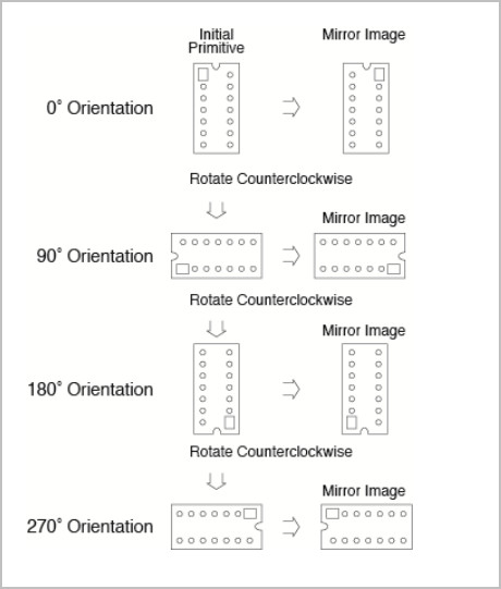
Example of rotation and mirroring as viewed from the top. Graphic from IPC-2581B standards documentation section 3.3.
So if a CAD file is imported into the Unisoft software and it does not explicitly define the rotation of a components then Unisoft will set the rotation to the IPC7351B Level A standard automatically.
However if the CAD file data explicitly defines the rotations of the components then on importing of the CAD file those rotations are used. If desired the Reset Rotation feature can be used to override these rotations and set them back to the standard.
The Reset Rotation feature of the Unisoft software will reset components back to the IPC7351B Level A zero degrees standard and many customers find this feature useful to normalize their component rotations. This is especially true if they are electronic contract manufacturers and deal with many different customers CAD files which sometimes exhibit different rotations for the same component package orientation.
The Reset Rotation feature does not alter the current pin positions of
any components on the display. It only modifies the rotation indicated for the
component, if necessary. For example, if IC component U1 has pin 1 in the upper
right corner before resetting the rotation, it will still be in the upper right
corner afterwards.
The following rotations are normally correct for 2 pin component packages per the IPC-7351B Level A zero degrees orientation standard:
| Degrees of rotation for component package per IPC-7351B Level A zero degrees orientation standard | Top side rotations indicated on the Unisoft software display for 2 pin components viewed from the top side | Bottom side rotations indicated on the Unisoft software display for 2 pin components viewed from the bottom side |
|---|---|---|
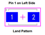
| 0 | 0 - (0 clicks of 90 CCW) - example pin 1 to left of 2 | 0 - (0 clicks of 90 CW) or (0 clicks of 90 CCW) - example above pin 1 to left of 2 |
| 45 | 45 - (0.5 clicks of 90 CCW) | 315 - (3.5 clicks of 90 CW) or (0.5 clicks of 90 CCW) |
| 90 | 90 - (1.0 click of 90 CCW) - example pin 1 below pin 2 | 270 - (3.0 clicks of 90 CW) or (1.0 click of 90 CCW) - example above pin 1 below pin 2 |
| 135 | 135 - (1.5 clicks of 90 CCW) | 225 - (2.5 clicks of 90 CW) or (1.5 clicks of 90 CCW) |
| 180 | 180 - (2.0 clicks of 90 CCW) - example pin 1 to right of 2 pin | 180 - (2.0 clicks of 90 CW) or (2.0 clicks of 90 CCW) - example above pin 1 to right of 2 pin |
| 225 | 225 - (2.5 clicks of 90 CCW) | 135 - (1.5 clicks of 90 CW) or (2.5 clicks of 90 CCW) |
| 270 | 270 - (3.0 clicks of 90 CCW) - example pin 1 above pin 2 | 90 - (3.0 click of 90 CW) or (1.0 clicks of 90 CCW) - example above pin 1 over pin 2 |
| 315 | 315 - (3.5 clicks of 90 CCW) | 45 - (0.5 clicks of 90 CW) or (3.5 clicks of 90 CCW) |
The following rotations are normally correct for 3 pin and greater component packages (IC's, etc.) per the IPC-7351B Level A zero degrees orientation standard:
| Degrees of rotation for component package per IPC- 7351B Level A zero degrees orientation standard | Top side rotations indicated on the Unisoft software display for 3 pins or greater components viewed from the top side | Bottom side rotations indicated on the Unisoft software display for 3 pins or greater components viewed from the bottom side |
|---|---|---|
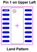
| 0 | 0 - (0 clicks of 90 CCW) | 0 - (0 clicks of 90 CW) or (0 clicks of 90 CCW) - example above pin 1 upper left |
| 90 | 90 - (1.0 click of 90 CCW) | 270 - (3.0 clicks of 90 CW) or (1.0 click of 90 CCW) - example above pin 1 upper left |
| 180 | 180 - (2.0 clicks of 90 CCW) | 180 - (2.0 clicks of 90 CW) or (2.0 clicks of 90 CCW) - example above pin 1 lower right |
| 270 | 270 - (3.0 clicks of 90 CCW) | 90 - (1.0 click of 90 CW) or (3.0 clicks of 90 CCW) - example above pin 1 upper right |
As can be seen above topside rotations are straight forward but the bottom side rotations are less so.
The PCB assembly ( PCBA ) manufacturing production equipment that needs this rotation information, such as Pick & Place assembly or AOI equipment, may differ on what rotations it expects between vendors and models and normally the Unisoft software will take care of any corrections.
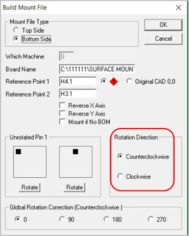
If modifying the rotation is desired controlling the rotation can be done in a number of ways within the Unisoft software. Besides the Reset Rotation feature explained above, for example, in the window below, although it is normally not the standard, the CCW rotation can be adjusted to CW. For details on rotation modification options go to Rotations - Rotation modification options.
Rotations - Component zero orientation info IPC-7351
Rotations - Rotation modification options