Adding Non-Electrical and Non-Electronic Parts, Accessories, Processes,
etc.
This feature of the Unisoft
software allows you to add parts, processes, and other items that are not
part of the actual electrical circuitry on the PC board. These elements can
then be assigned to individual assembly process steps and treated like any
other step within the Unisoft software. You can add just a few additional
steps or, if desired, define the entire PCB assembly process—from the
pre-assembly stage to the main assembly stage, and continuing through the
point at which the fully assembled PCB is integrated into its subassembly.
For instance, if you need to
manually add pcb card ejectors, you can enter that item along with
corresponding annotation text, notes, and pictures. You can then apply it to
a specific assembly step and treat it just like any other process step in
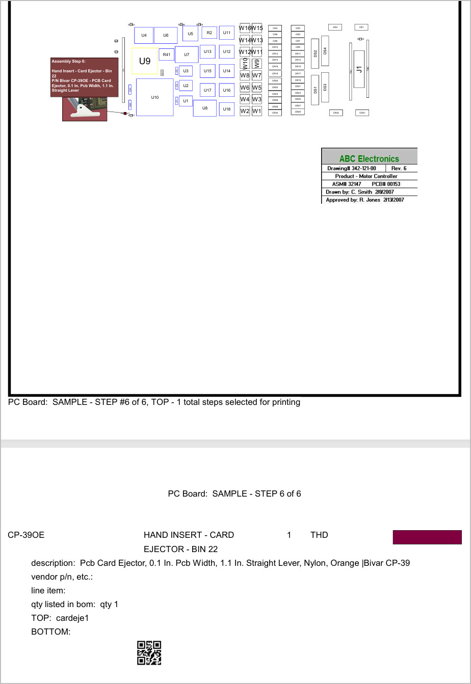
the Unisoft software. Then as in the figure below, you can print or
display that assembly step.
Below are some examples of
non-electrical parts and processes that can be involved in completing a PCB
assembly. You may also create as many steps as desired—for example, you can
extend your steps to include pre-assembly and post-assembly processes and
examples are listed below.
ASSEMBLY:
- Adhesives - Epoxy Or Silicone Potting For Moisture Or Vibration Resistance
- Adhesives - Conformal Coating Protective Layer Encapsulation
- Adhesives - Hot Melt Glue / RTV Silicone / Double-Sided Tape / Adhesive Strips For Securing Parts
- Adhesives - Loctite / Threadlocker For Securing Screws And Fasteners
- Adhesives - Thermal Epoxy Or Paste For Bonding Heatsinks
- Backplane Systems, Enclosures, Industrial Racks, Etc.
- Bezels
- Brackets
- Cables
- Cable Routing And Securing – Zip Ties, Cable Guides, Adhesive Mounts
- Card Guides Or Rails – For Insertion Into Chassis Slots
- Cleaning (E.G., IPA Wash) – Removing Flux Or Residue
- Connectors And Sockets (Non-SMD)
- Card Ejectors
- Card Stiffeners
- Edge Connectors
- Foam
- Frames
- Gaskets
- Heatsinks
- Inspection Checklists – To Confirm Final Build Completeness
- Insulator Pads
- Labels
- Mounting Brackets Or Flanges – To Secure The PCB In Enclosures
- Protective Covers
- Screws, Nuts, And Washers – For Fastening PCBs To Standoffs Or Enclosures
- Security Seals / Tamper Evident Tape – Compliance Or Warranty-Related
- Serial Number Tags
- Shields (EMI/RFI) - Metal Shielding Cans, Etc. For EMI Shielding
- Spacers / Standoffs
- Testing Processes - Functional / Electrical Testing
PRE-ASSEMBLY:
- Data Intake & Review - CAD, BOM, Gerbers, etc.
- Collect and verify:
- BOM (Bill of Materials)
- Pick-and-place file (XY, XYR, CAD, Centroid, etc.)
- Gerber files (including paste, mask,
silkscreen, copper layers, drills)
- Netlist
- Drill file (Excellon
format or similar)
- Special customer instructions (e.g., polarity
markings, DNPs)
- PCB stack-up or fabrication drawing
- Test
procedures or software (if provided)
- Assembly drawings or mechanical
drawings
- Stencil design (or create internally)
- Engineering Review and DFM/DFT Checks
- Confirm component clearances and spacing
- Check for potential tombstoning, insufficient pads, and unmasked vias
-
Identify fiducials, tooling holes, board edge clearance
- Assess for ICT
or flying probe access (DFT)
- Validate thermal profiles for reflow
compatibility
- Evaluate if fine-pitch BGAs, via-in-pad, or
bottom-terminated components require special handling
- Check for mixed
technology (SMT + THT) and evaluate soldering approach
- BOM Validation & Parts Management
- Cross-check:
- Part number consistency
-
Package types and orientations
- Reference designators match
pick-and-place data
- DNPs (do not place) clearly indicated
- Check:
- Inventory availability
- Procurement of missing parts
- Lead times
on long-delivery items
- Review:
- Obsolete or EOL parts and
alternatives
- Manufacturer part number conflicts
- Handle:
-
Special storage needs (MSL, ESD)
- Customer-supplied parts (consigned
inventory)
- PCB Fabrication Coordination
- Finalize:
- PCB specs
(layer count, finish, copper weight, etc.)
- Material (e.g., FR4, Rogers,
polyimide)
- Impedance control if needed
- Panelization:
- Define
panel array layout, tooling strips, fiducials, breakaways (V-score or routed
tabs)
- Account for wave solder pallets if needed
- Confirm:
- Bare
board inspection requirements
- Certificates of conformance (RoHS,
lead-free)
- Stencil Creation / Approval
- Generate stencil aperture
data (from paste Gerber)
- Adjust:
- Paste reduction, rounded
apertures, home-plate designs, etc.
- Select:
- Stencil thickness
(typically 4–8 mils)
- Stainless steel vs. nano-coated
- Coordinate:
- With vendor or create in-house
- Approval before manufacturing
-
Assembly Documentation Package Creation
- Create or validate:
-
Assembly drawings with polarity and part markings
- Placement printouts
for operators and inspectors
- Process flowcharts by step (paste print,
placement, reflow, inspection, etc.)
- Rework instructions and customer
quality standards
- Barcoding and labeling instructions
- Include:
- Revision control documentation
- Traceability requirements
-
Serialization methods if requested
- Parts Receiving, Inspection & Storage
- Receive components:
- Customer consigned or from procurement
- Perform:
- Incoming quality inspection
- Visual and dimension checks
if needed
- Lot and date code recording
- Log:
- MSL handling
(track exposure time and re-bake if necessary)
- Store:
- In ESD-safe,
humidity-controlled environments
- Kitting & Job Prep for Production Floor
- Pull all components from inventory and group by job
- Label
and organize:
- Per feeder or tray location
- Separate SMT vs. THT
bins
- Include:
- Extra parts for setup, attrition, and testing
-
Print and include:
- Feeder setup sheets
- Staging checklists
-
Operator instructions
- Confirm:
- All materials (boards, parts,
stencil, fixtures) are gathered
- Floor traveler or job packet assembled
- QA double-check:
- Complete kit integrity before releasing to the floor
- Machine Programming & Setup
- SMT Pick-and-Place:
- Load placement
files into machine software
- Map parts to feeder slots
- Assign
nozzle tools and check orientation
- Screen Printer:
- Load stencil
and align fiducials
- Load paste profile (pressure, speed, snap-off)
-
Reflow Oven:
- Select or tune temperature profile based on solder paste
- AOI/Inspection Systems:
- Program inspection for reference components
- ICT/Functional Test:
- Load test software or bed-of-nails test program
- Production Scheduling & Readiness
- Book:
- Production time on
assembly line
- Assign:
- Operators, inspectors, and support personnel
- Perform:
- Line setup dry run (optional)
- Pre-checks: stencil,
feeders, boards, air pressure, oven temp
- Conduct:
- Pre-run team
meeting (review process flow, risks, special instructions)
- Final QA
signoff:
- Confirm release-to-floor checklist complete
POST-PCB ASSEMBLY:
- Inspection & Testing
-
Visual Inspection (manual or with magnification)
- Automated Optical
Inspection (AOI)
- X-Ray Inspection (for BGAs and inner-layer defects)
- In-Circuit Testing (ICT) – Bed-of-nails or fixtureless
- Flying
Probe Testing – Non-contact probing
- Functional Testing (FCT) –
Power-up and run actual firmware/software
- Boundary Scan / JTAG
- Power-On Self Test (POST)
- Signal Integrity / Impedance Testing –
For high-speed designs
- HiPot Testing – High-voltage insulation
resistance testing
- Continuity Testing – Open/short detection
-
Fixture Setup and Validation – Custom test fixtures for ICT/FCT
- Cleaning & Residue Removal
- Aqueous Cleaning – Batch or in-line
-
Solvent-Based Cleaning – For no-clean flux or special chemistries
-
Ultrasonic Cleaning
- Manual Cleaning with IPA
- Deionized Water
Rinse
- Drying Ovens / Forced Air
- Identification, Labeling &
Documentation
- Serial Number Labels (Barcodes, QR codes, DataMatrix)
- MAC Address or UID Assignment
- Revision Control Labels
- Work
Traveler Updates / Routing Sheets
- Test Logs and Certifications
- Photographic Documentation
- Digital Traceability Logs (via MES
system)
- Protective Coatings & Materials
-Conformal Coating
(Spray, Dip, Selective)
- Potting and Encapsulation – Full or selective
- Underfill for BGAs
- Edge Sealing
- Thermal Interface Material
Application
- Vibration Dampening Gel or Foam
- Mechanical
Assembly
- Mounting to Metalwork / Frames / Chassis
- Attachment of
Heatsinks or Thermal Pads
- Screws, Rivets, Clips, Stand-Offs
Installation
- Mounting of Non-Electrical Components (card ejectors,
guides, stiffeners)
- Integration into Racks, Subassemblies, or Final
Products
- Environmental and Stress Testing
- Burn-In Testing – Run
for extended periods under load
- Thermal Cycling
- Environmental
Stress Screening (ESS)
- Vibration Testing
- Humidity Chamber
Testing
- Salt Fog / Corrosion Testing
- Electrostatic Discharge
(ESD) Testing
- EMI/EMC Pre-Compliance Testing
- Software &
Configuration
- Firmware Upload / Flash Programming
- Bootloader
Programming
- Serial Number / MAC / Configuration File Loading
-
Security Key Injection (if applicable)
- BIOS/UEFI or CPLD/FPGA
Programming
- Product Configuration and Calibration
- Validation
of I/O ports, wireless modules, sensors, etc.
- Final QA / Quality
Assurance
- Final Quality Audit
- Operator Sign-Off on Build Traveler
- First Article Approval (if applicable)
- MRB (Material Review
Board) Handling
- Customer-Specific QA Steps
- Packaging
Inspection
- Regulatory Labeling (UL, CE, FCC, RoHS, etc.)
-
Packaging for Shipment
- Anti-Static (ESD-Safe) Bagging
- Moisture
Barrier Bagging + Desiccants + Humidity Indicators
- Foam, Bubble Wrap,
and Bracing for Fragile Units
- Custom Packaging / Kitting per Customer
Requirements
- Serialized Labeling on Box
- Palletization & Load
Stability Checks
- Shipping Documents, BOLs, Customs Forms
-
Customer Delivery & Field-Readiness
- Final Assembly into System Enclosures
(if required)
- User Documentation or Manual Insertion
- Software
Licensing and Activation Keys
- Final Configuration Testing in System
Environment
- Customer-Specific Checklist Completion
- On-Site
Install Kits, Tools, or Instructions
- Integration with ERP or
Inventory System for Shipment Notification
- Regulatory &
Compliance
- RoHS / REACH Declarations
- UL / CE Certification
Processes
- Export Control (ITAR, EAR)
- Conflict Minerals
Reporting
- First Article Inspection Reports (FAIR)
- IPC-A-610
Class Verification (Class 2 / Class 3 standards)
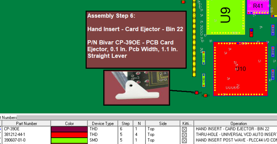
Here is an example of how a card ejector can be
added.
For this example, we’ve added an
extra step—Step 6—to manually insert a non-electrical part, specifically a
card ejector, onto the PCB.
Note: The first step shown below is the only required step when using the
feature “Non-Electrical Parts, Accessories, Processes…”. All
other steps are optional and use additional features
of the software to aid in building fast and accurate assemblies. These
features allow you to assign process step numbers, pictures, text, etc. to
generate completed assembly documentation.
The process
described below assumes a basic working knowledge of the Unisoft software.
Please contact us if you would like a review of this feature.
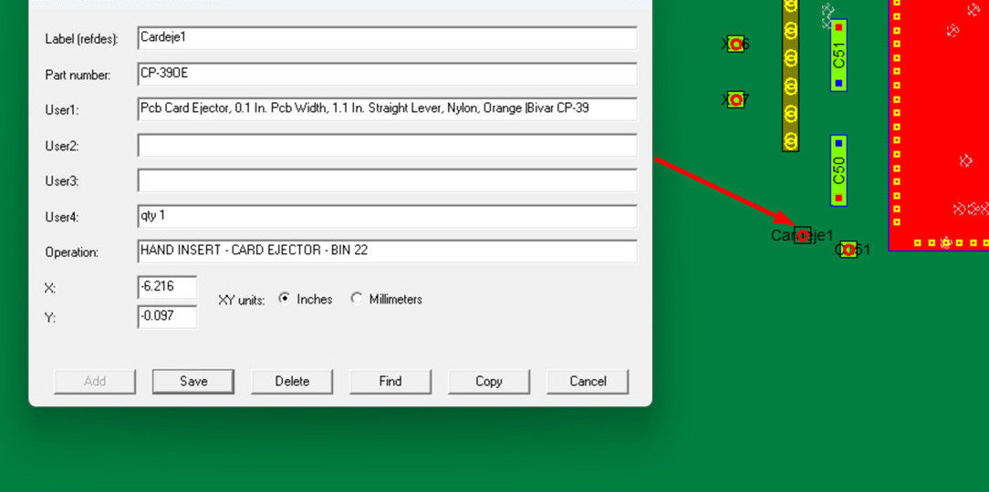
The first step is
to click the “Non-Electrical Parts, Accessories, Processes…” option
found under either the “Assembly Sheets/1st Article” menu or the “Edit”
menu. After selecting the menu item, a cursor appears with the letters "NE"
next to it. The user then moves the cursor to either an empty area on the
board to create a new item, or to an existing non-electrical item to edit or
delete it, and left-clicks the mouse. If the cursor is in an empty area, an
entry window with blank fields appears. The user fills in the fields in the
window and clicks “Add” to create a new non-electrical item at the cursor.
The new item, labeled "Cardeje1" as its reference designator, is added along with its part number and
other relevant details.
Note: From this window, you can also
copy, find, and delete these Non-Electrical Parts.
At this point, for this non-electrical item just
created,
we have access to all the standard features of the Unisoft software that are
available for any electrical component on the PC board. So we can assign it
to any process step, add annotations, print it out, blink it, check it off
for inspection, etc.—whatever we want to do.
Next, we create and assigned one annotation
containing text and another containing a picture.
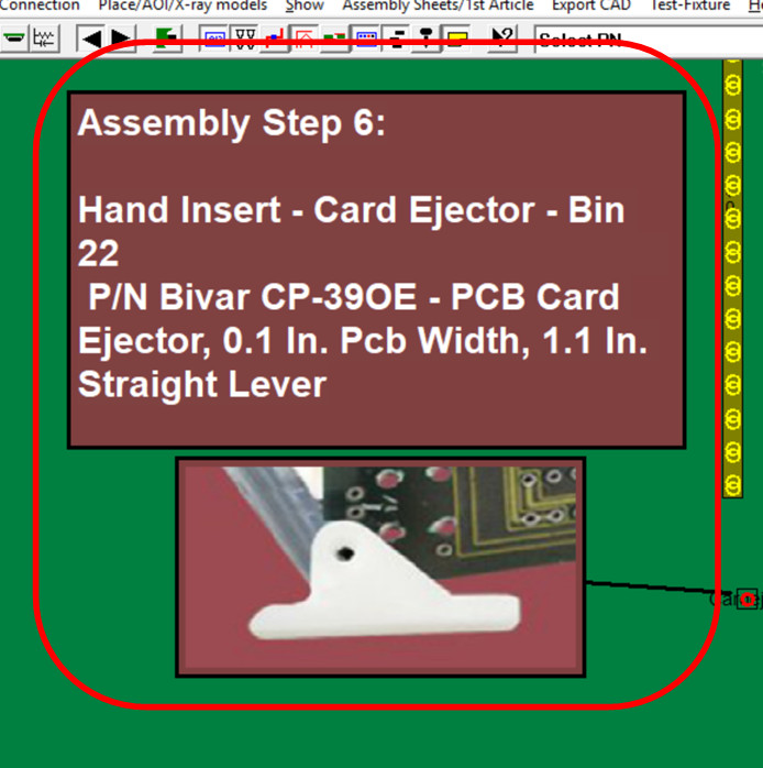
We then associate this
non-electrical assembly operation with Process Step Number 6.
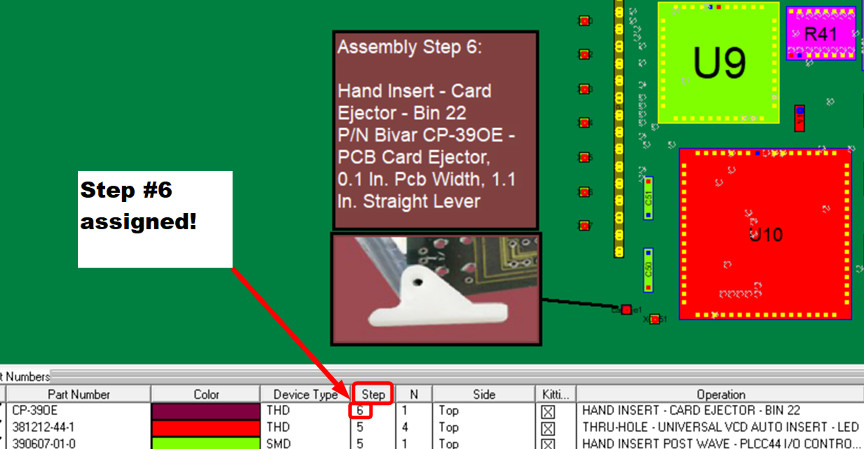
In the example shown in the figure
below, we use the standard Unisoft “Print Assembly Document” feature to print Step
Number 6. If you choose not to print, the operator can simply work from the
on-screen display and complete the assembly—just like with any other step
operation.