The Unisoft software allows you to import an annotation of any type, for example a photograph of the actual PC Board, and have that in the foreground or background of the displayed elements.
So a graphic such as a .bmp, .gif, .jpg, .png, .tif, etc. can be overlaid and rendered either in the front or the back of what is currently displayed.
That graphic can further be aligned and anchored to exact points on the display. So for example component pins on the graphic can be aligned to the component pins on the display.
Examples might be to use your favorite or a free third-party gerber viewer such as Gerbv to display the gerber layer and then snap shot that layer to bring in the layer(s) that you want. If this layer was the gerber solder mask layer then component pad footprints can be overlayed and lined up to those component pins on the Unisoft display to aid footprint inspection, assembly, etc.
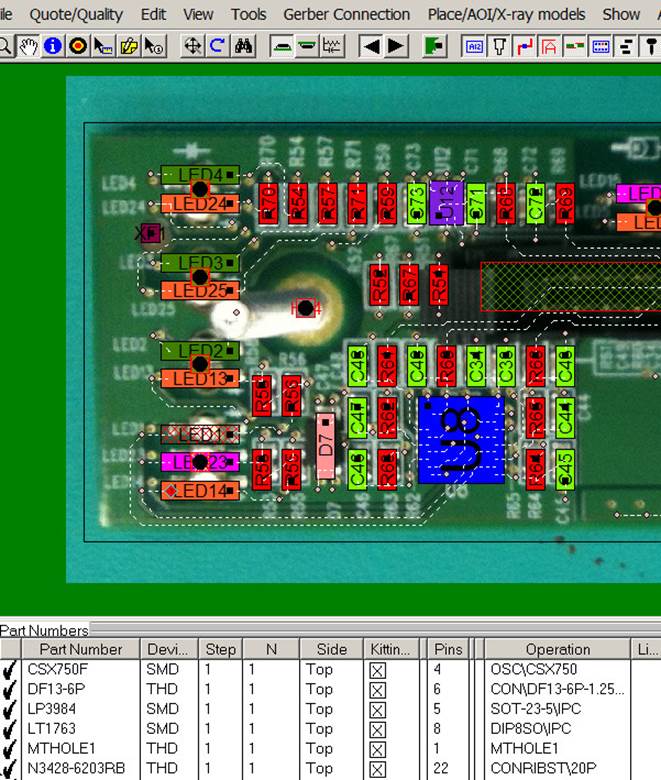
Or a photograph of the bare or loaded PCB assembly ( PCBA ) can be used as the overlay.
Customers find this feature very useful, for example the colors that are assigned to components can be overlaid on top of the actual photograph of the PCB assembly ( PCBA ) to aid assembly by creating more detailed process assembly documents and also for First Article Inspection, footprint crosschecking, etc. and so there is more realism when blinking by part number for inspection check off.
EXAMPLE OF A PCB assembly ( PCBA ) WITH NO IMAGE OVERLAYED IN THE BACKGROUND:
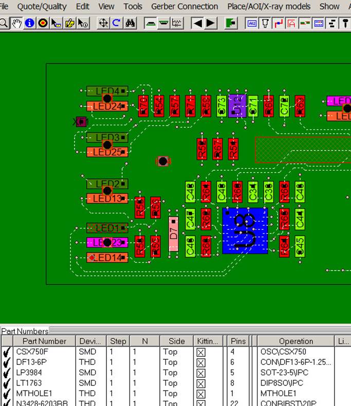
EXAMPLE OF A PCB assembly ( PCBA ) WITH AN IMAGE OVERLAYED IN THE BACKGROUND:
TO USE:
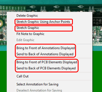
Create an Annotation and add a graphic as usual. Next click on the Annotation and in the window that appears select "Send to Back of PCB assembly ( PCBA ) Elements Displayed". Then move the annotation to line it up in one corner with the PCB assembly ( PCBA ) displayed elements and select "Stretch Graphic" to align it over the other PCB assembly ( PCBA ) displayed elements.
Note to get more precise lineups of graphics, the "Stretch Graphic Using Anchor Point" feature can be used and follow the procedure there.
In addition to the "Send to Back of PCB assembly ( PCBA ) Elements Displayed" feature there are three additional options to overlay the annotation graphic above or below the elements on the display. These three options are "Send to Front of PCB assembly ( PCBA ) Elements Displayed", "Send to Front of Annotations Displayed", and "Send to Back of Annotations Displayed".
Related information:
Assembly documents - adding steps to part numbers
Assembly documents -
adding substeps to part numbers
Assembly documents -
manual "tutorial 1 - creating assembly/process sheets, annotation overlays and kitting labels"
Assembly
documents - printing assembly documents
Assembly documents -
kitting labels-1
kitting labels-2
kitting labels-3
Assembly documents - multiple pages per step
Assembly documents -
powerpoint and custom types
Assembly
documents - editing multiple assembly steps
Assembly documents -
for paperless assembly instructions when using the display only for slide
line pcb assembly, etc.
Barcodes on the display and assembly
documents