- Software Products
- Trial Software
- CAD Translation
- Testimonials
- Overview
- Pricing
- Knowledge Base
- Contact Us -
- Languages
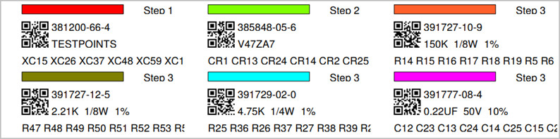
Creating assembly process or inspection documents is straightforward using Unisoft software. Component part numbers can be broken down into steps, with unique colors and brush patterns assigned to each part number. This allows for the creation of assembly or inspection process documents and kitting labels of various types, a sample of which is shown in the following two figures.
The following process
outline provides a brief overview of creating process assembly or inspection
documents. It assumes some basic working knowledge of the software, so
certain fundamental steps will not be detailed.
For more details than those outlined below, contact
Unisoft or refer to the manual section "Tutorial 1 — Creating assembly/process
sheets, annotation overlays, and kitting labels" by
clicking here
and following the procedure outlined.
There are basically four steps to creating assembly or inspection documents:
Step 1. For the process outlined here we are using the sample3.f2b board data file located in the directory c:\program files (x86)\unisoft\data-files . You can open that PCB file if you wish.
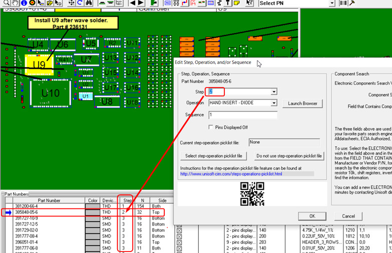
Next for our sample PCB assembly in the figure below,
Step 1 is assigned to the first part number, Step 2 to the second part number,
and Step 3 to the remaining part numbers.
As illustrated in the
figure below, this is done by double clicking on the part number in the
Smart Color window at the bottom of the display, then in the "Edit Steps,
Operations, and/or Sequence"
window, edit the "Step" field to
the desired number. Click "OK" when finished.
If desired, you can
further add Substeps to these steps to further breakdown these operations.
Note: When a PCB is first imported into the Unisoft software all part numbers are assigned to Step 1.
Step 2. At this point, either automatically or manually assign colors and brush patterns to part numbers and components.
Before the colors and brush patterns are assigned to the part numbers and components, you
can choose which ones you wish to use. To do this, as in the picture
below, first click "Color All P/N's" then click "Select Colors/Brush
Patterns". In the "Select Colors/Brush Patterns" window, select the colors
and brush patterns you want by
checking or unchecking the boxes desired. Click "OK" when finished.
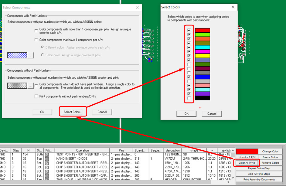
Now, in our sample PCB in the figure below, the colors and brush
patterns are assigned automatically, so red is assigned to Step 1, green to
Step 2, and so on. To do this, first click
"Color All P/N's,"
then in the "Select Components" window, click the assign
color settings that you wish (use the settings in the picture below), and then click "OK". The colors and brush
patterns are then assigned to
the part numbers and components.
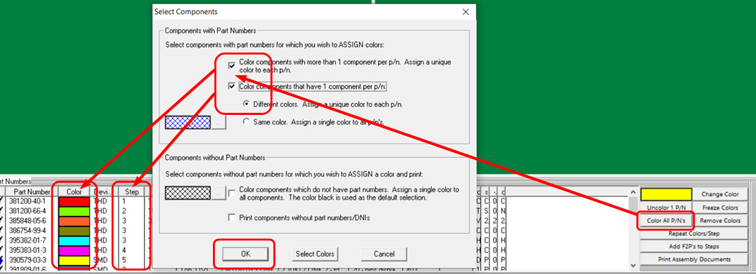
Note: Components without part numbers, usually referred to as Do Not Install
(DNI) components, are colored black by default when the "Color Components
Which Do Not Have Part Numbers..."
box is checked.
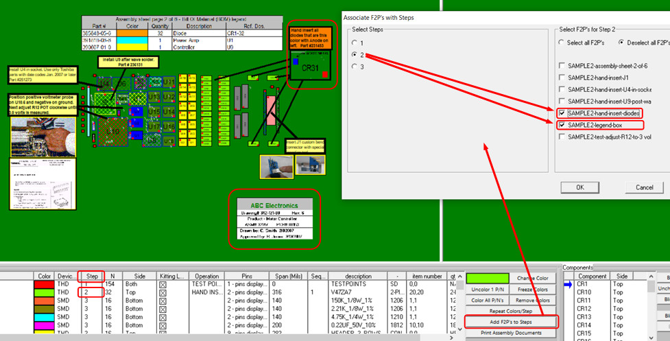
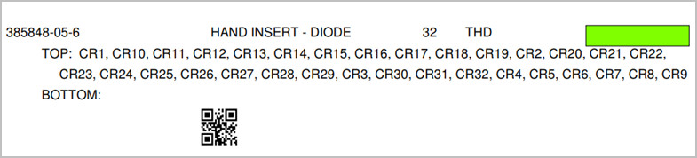
Step 3. Optionally add annotation overlays to
steps. For example, in the figure below, the annotation overlays named
"SAMPLE2-hand-insert-diodes" and "SAMPLE2-legend-box", that are outlined
in red
on the image below, are assigned to Step number 2. So, when Step 2 is printed,
only these two annotation overlays will appear on that step.
To do this, as illustrated in the figure below, click on "Add F2P's to Steps".
In the "Associate F2P's with Steps" window, select the step and then the desired
overlay .F2P document or documents you
wish to be displayed at that step.
Click "OK" when finished.
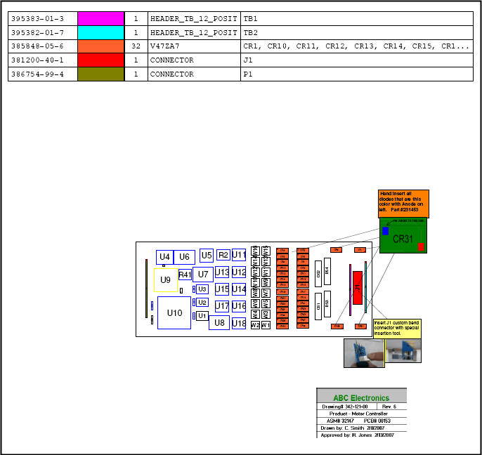
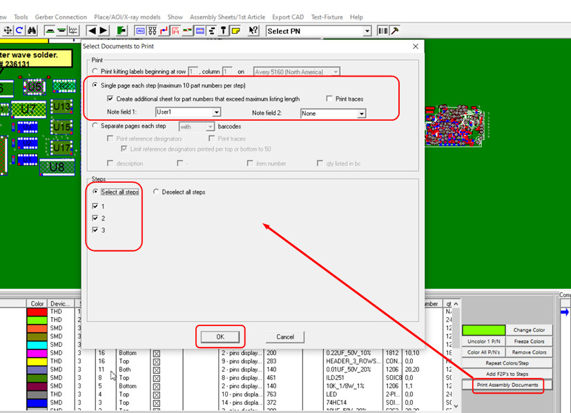
Step 4. Print out the assembly document using
the format shown in the figure below by selecting all steps and choosing the
"Single page each step..." option. Note, this
"Single page each
step..." format, while less detailed, is popular because it combines the
drawing and assembly load list on a single page for each step, making it
visually efficient for assembly operators.
To do this, first click
on "Print Assembly Documents" as shown in the picture below. Next, use the
settings illustrated in the figure below in the "Select Documents to Print"
window. Click "OK"
and choose the desired printer format, for example, print to
a PDF document, printer, etc.
If desired,
PCB photos,
gerber silkscreen overlays, part number
barcodes, and other options can be added to the documents.
Note: There are several options for different types of process documents
that can be created. For example, the
"Separate pages
each step" option in the "Select Documents to Print" window creates a
process document with more detail but more pages. Another
example is using
Microsoft Powerpoint to create the process document.
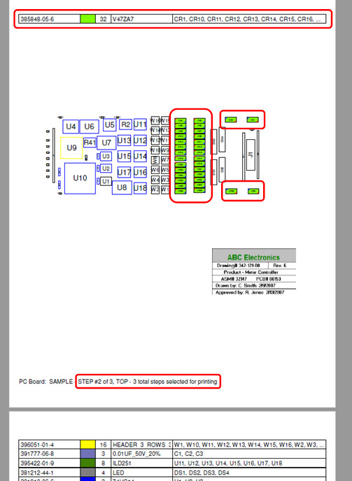
The assembly document created contains all three steps with unique
colors. For example, as can be seen in the figure below, for Step 2 in the
printout, the part number was assigned the color green, and all the components
with that part number are colored green.
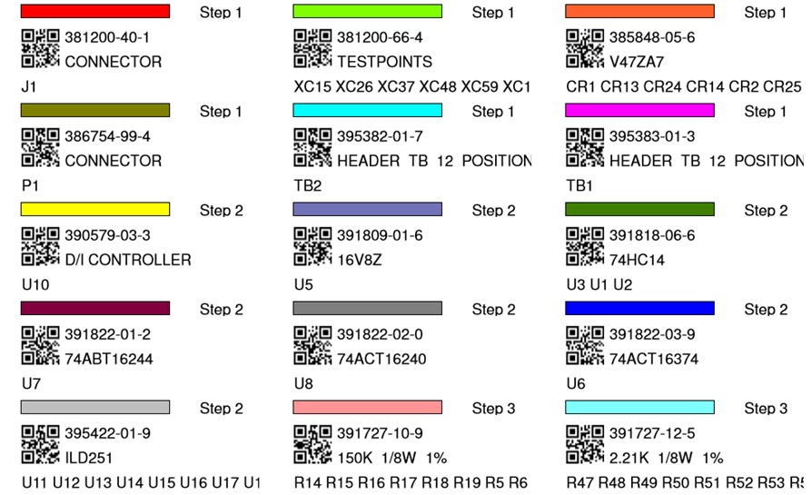
Matching kitting label documents of various types can
be created, as illustrated in the following two figures.
To do
this in the second figure above in the "Select Documents to Print"
window select "Print kitting labels beginning at row...". Then click
"OK" and choose the desired printer format,
for example, print to
a PDF document, printer, etc.
Additional similarly related Information:
Assembly documents - adding steps to part numbers
Assembly documents -
adding substeps to part numbers
Assembly documents -
manual "tutorial 1 - creating assembly/process sheets, annotation overlays and kitting labels"
Assembly
documents - printing assembly documents
Assembly documents - creating kitting labels
Assembly documents -
kitting labels-1
kitting labels-2
kitting labels-3
Assembly documents - single page per step.
Assembly documents - multiple pages per step
Assembly documents -
powerpoint and custom types
Assembly
documents - editing multiple assembly steps
Assembly documents - add pcb photos, etc. to the display background
Assembly documents -
for paperless assembly instructions when using the display only for slide
line pcb assembly, etc.
Barcodes on the display and assembly
documents