- Software Products
- Trial Software
- CAD Translation
- Testimonials
- Overview
- Pricing
- Knowledge Base
- Contact Us -
- Languages
A printed circuit board (PCB) component is an electrical part that goes into
making the assembly of a circuit board. There may also be non-electrical parts
and services
needed for the assembly of the PCB.
PCB electrical components consists
of elements such as diodes, capacitors, fuses, resistors, IC's, etc.
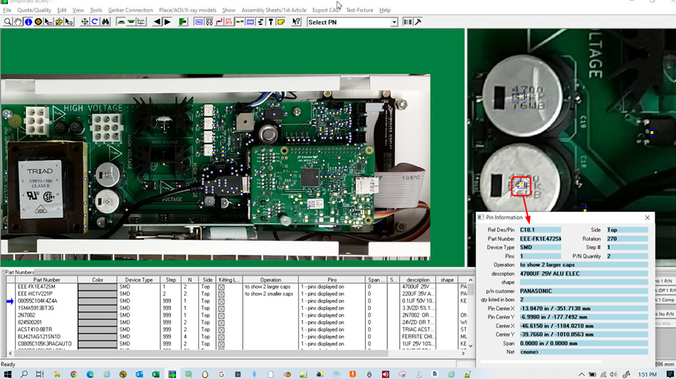
The
Unisoft software matches these electrical components defined in the PCB file
data which can be CAD files, Gerber files or XY center rotation files with the
electrical components listed in the Bill Of Material (BOM).
The names
for the matching electrical components on the PCB and BOM data files are
normally referred to as "reference designators".
The assembly of a PCB
may include non-electrical components such as board stiffeners, sockets, heat
sinks, stand-offs, push button caps, spacers, and additional services such as
AOI inspection and Flying Probe Testing, among others. Since these
non-electrical items in the BOM do not typically have a matching reference
designator in the PCB file data, they are not included in the Unisoft Pronto
software when the PCB is displayed.
Below are several methods and ideas for incorporating these non-electrical items
into the Unisoft Pronto software when displaying the PCB, enabling the handling
of these processes and the calculation of their costs. It is assumed you have some experiance using the Unisoft software,
contact Unisoft for training if needed.
NOTE:
On this webpage we are discussing how to add non-electrical parts listed in the
Unisoft Pronto series software (modules include ProntoVIEW-MARKUP, ProntoPLACE, ProntoAOI,
ProntoTEST-FIXTURE, ProntoSELECTIVE-SOLDERING and ProntoGERBER-CONNECTION) and
the methods listed below are usually adequate for most Electronic Manufacturers
to handle and cost these non-electrical parts during the assembly process. However
Unisoft has another software module called Unisoft CELLS MES Tracking software (
https://www.unisoft-cim.com/cells.php ) which is meant to do more complex
functions with PCB board and box build and maybe a consideration for some
Electronic Manufacturers for the handling of these non-electrical parts on the
PCB.
With the Unisoft Pronto series software a simple way to handle non-electrical
parts for assembly is to add pictures or any type of overlay with text, etc.
that may represent these non-electrical parts.
Link -
https://www.unisoft-cim.com/view-markup_download.htm#CREATING_.F2P_ANNOTATION_OVERLAYS
.
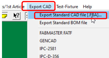
In this method the non-electrical parts are added to the exported Unisoft .FBA data file. The process in brief is:
- Import the PCB as normal into the Unisoft software.
- Export a .FBA file.
-
To the .FBA file add the non-electrical parts as a dummy line entry. For
example board stiffeners or stand-offs, push button caps, spacers, sockets,
heat sinks,
etc.
- Reimport the .FBA file into the Unisoft software.
-
Import the BOM including the
non-electrical parts. Now these non-electrical parts have an
association in the Unisoft software similar to the electrical components.
note: each non-electrical part, you wish included, needs to have a unique
name in the BOM.
More detail for
this method follows. This process can be relatively quick maybe 5 to
10 additional minutes for a project.
In this method to add
non-electrical parts that are in the BOM first import your standard
type CAD data as you would normally. Then export out a .FBA file which
contains data that represents the PCB just imported.
Example .FBA:
*XY
1 - -RDLTCH U5 3 X -4.600
Y 2.000 T S
1 - -RDLTCH U9 40 X -5.425
Y 1.675 T S
At this
point in the .FBA file you would edit in the reference designators for the
non-electrical parts, for example for board stiffeners or stand-offs, push
button caps, spacers, sockets,
heat sinks,
etc. and you would use the same reference designator names for them that are
used in the BOM (Note:
each non-electrical part, you wish included, needs to have a unique name in
the BOM.).
Each non-electrical part added is inserted in a line on its own. The
only data in the line that needs to be unique is the non-electrical parts
reference
designator you are adding.
So you can
default using the same dummy type data in the fields in each line added.
For example the fields in red below can be repeated on each line:
9999, -, XXXXXX, 1, X, 0.000, Y, 0.000, T. So for each
line added enter
only the unique reference designator for the
non-electrical
parts as they are defined in the BOM as has been done with the 4 red
lines in the sample below.
*XY
1 - -RDLTCH U5 3 X -4.600
Y 2.000 T S
1 - -RDLTCH U9 40 X -5.425
Y 1.675 T S
9999 - XXXXXX
SOCKET1 1 X
0.000 Y 0.000 T
9999 - XXXXXX
SOCKET2 1
X 0.000
Y 0.000
T
9999 - XXXXXX
STDOFF1 1 X
0.000 Y 0.000 T
9999 - XXXXXX
PUSHB1 1 X
0.000 Y 0.000 T
9999 - XXXXXX
PUSHB2 1 X
0.000 Y 0.000 T
9999 - XXXXXX
SPACE1 1 X
0.000 Y 0.000 T
9999 - XXXXXX
AOI-INSPECTION-SERVICE 1 X
0.000 Y 0.000 T
9999 - XXXXXX
FLYING PROBE-TESTING-SERVICE 1 X
0.000 Y 0.000 T
Next
import the .FBA file into the Unisoft software as you would any other CAD
data file. At that point these new reference designators are part of the
Unisoft .F2B database created for this PCB.
Next import the BOM as
normal and the newly introduced
non-electrical
items reference designators will be associated to the bom data for
those reference designators.
Again each non-electrical item, you wish included, needs to have a unique
name in the BOM.
At this point you can add
any picture graphics, text, etc. as you normally would to enhance the
assembly instructions.
Also these new non-electrical parts can
be assigned a cost, their own process step number, unique coloring, operation note information,
etc.