- Software Products
- Trial Software
- CAD Translation
- Testimonials
- Overview
- Pricing
- Knowledge Base
- Contact Us -
- Languages
Related information:
Quoting by span: Assembly Cost or Time by Component Count Span Report for
Quoting
Quoting by p/n:
Assembly or Parts Cost or Time by Part Number Report for Quoting
Quoting/quality from solder joints: Solder Joint Count Report. Defect Per
Million Operations (DPMO)
Cycle Times
When quoting or running assembly production for a PCB assembly (PCBA) project, it is always best to have the full CAD files. However, Electronic Contract Manufacturers and some OEMs sometimes only receive Gerber files instead of CAD files for quoting a potential project. This can be a time-consuming process.
The following procedure provides a fast way to generate a cost quote when only Gerber files are available. The process assumes that you have some experience working with Gerber files using the Unisoft software. Please contact Unisoft with any questions or for training.
Essentially, the procedure involves grouping similar shapes together, allowing cost, time, and other factors to be assigned for quoting purposes.
Note: This method, outlined below, facilitates quick quoting when only Gerber files are available. It groups similar shapes with components of the same pin count and provides a total for each group. At that point, each group is assigned a unique cost or assembly time, generating a quote.
However, the Unisoft .F2B database file
created through this process will not have correctly matched reference
designators. As a result, it cannot be used for many of Unisoft's standard
production assembly features, such as creating process assembly documents,
first article inspection, programming assembly machines, or AOI machines.
Depending on your needs, you may want to invest the
extra time (approximately 5 to 10 minutes per 100 components) to create
components in the standard way with correct reference designators, when
using only Gerber files. This approach ensures that the resulting .F2B
database file can support both cost quoting and other essential production
assembly features of the software.
To this point, this webpage proofed using AI in 2025
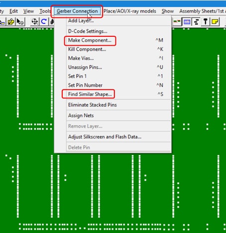
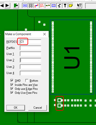
PROCEDURE: After importing the gerber file(s) into the Unisoft software use the standard procedure to MAKE a component and FIND SIMILAR SHAPE from the GERBER CONNECTION menu.
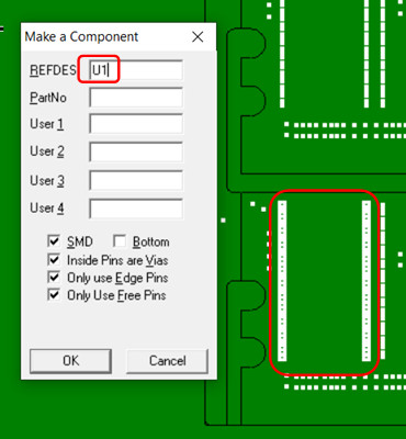
In this example we made a component with reference designator name U1 . Note: The reference designator name can be almost anything you wish because we are not taking the time in this procedure to actually match the reference designators to what is on the PCB. For example if you wish you can use a reference designator that more closely fits the device shape for example SMD66P1 .
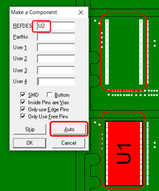
Next the component that was defined is selected and then the FIND SIMILAR SHAPE feature is selected and the AUTO button is clicked.
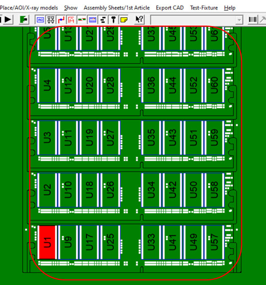
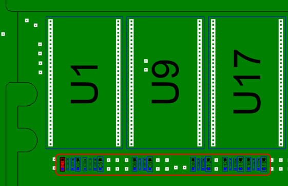
The result is all the components of that shape are automatically found and given unique reference designators.
This process above is repeated for each unique shape and a new component reference designator name is used for each unique shape and in the example below it is C1. Note: The reference designator name can be almost anything you wish because we are not taking the time in this procedure to actually match the reference designators to what is on the PCB. For example if you wish you can use a reference designator that more closely fits the device shape for example SMD0402P1 .
The components for the shape are automatically found and given unique reference designators .
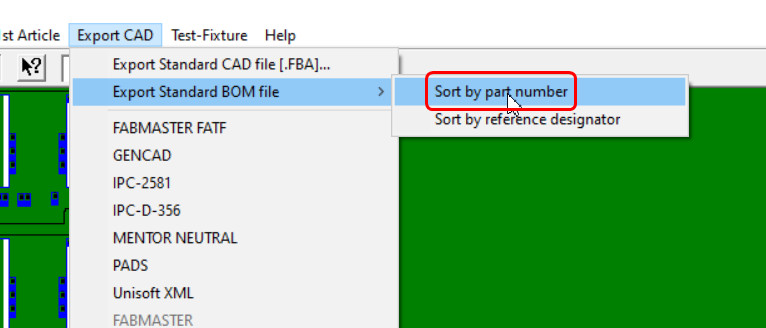
Next from the EXPORT CAD menu select EXPORT STANDARD BOM FILE and click SORT BY PART NUMBER and save the file and you are finished.
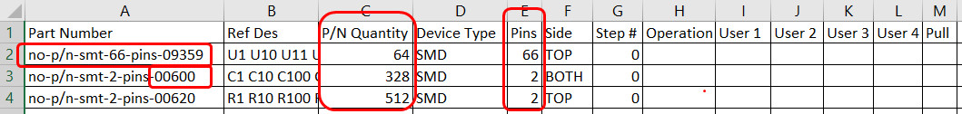
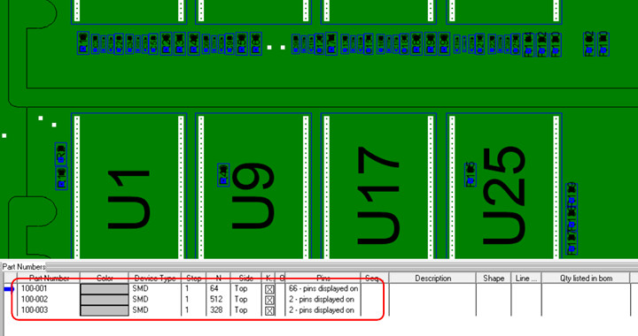
The figure below represents the file produced which is a tab delimited ASCII file which can be imported into Excel, etc.
In the file like shapes are grouped together and the total quantity of components for each group is given in the P/N QUANTITY field. The number of pins on each group is listed in the PINS field. At this point the groups are given unique cost or assembly time and a quote is generated.
The part number field is generated automatically from the uniqueness of the shape, for example for the part number below no-p/n-smt-2-pins-00600 it indicates it is an SMT device and that it is 2 pins total.
The last 5 digits of the part number is the greatest distance between any 2 pins on the device and it is in units of 0.1 of a mil (one ten thousandth of an inch). So for part number no-p/n-smt-2-pins-00600 it is 60 mils between the exact centers of pin 1 and 2 on the device.
You can quote with the procedure above so there is no need to proceed any further. However below if you want you can create and import a dummy BOM and by doing so you can get a small amount of additional grouping data. Please contact Unisoft for more details.
Next optionally a small dummy Bill Of Materials (BOM) is imported into the Unisoft software. For example:
100-001     U1-U1000
100-002     C1-C1000
100-003     R1-R1000
After importing the dummy BOM the result is those components and pins are included in the totals for the PCB.
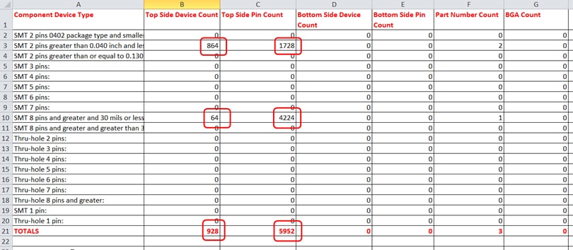
Next click the DEVICE COUNT BY COMPONENT SPAN report.
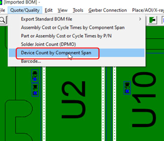
The DEVICE COUNT BY COMPONENT SPAN report is created with the sizes, component counts, device pins solder joints, etc. These totals can be used to aid in creating a job quotation.
Another report style that may be useful is the Solder Joint Count (DPMO). To create this report click SOLDER JOINT COUNT (DPMO).
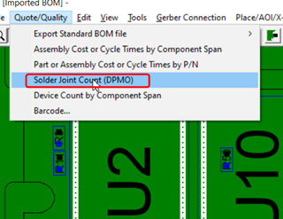
The Solder Joint Count (DPMO) report is created with the total solder joints of the various types listed at the top.
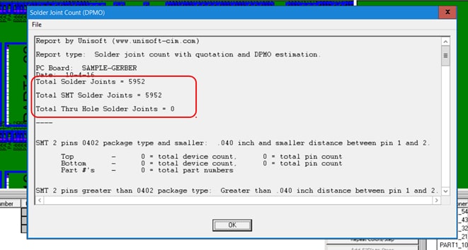
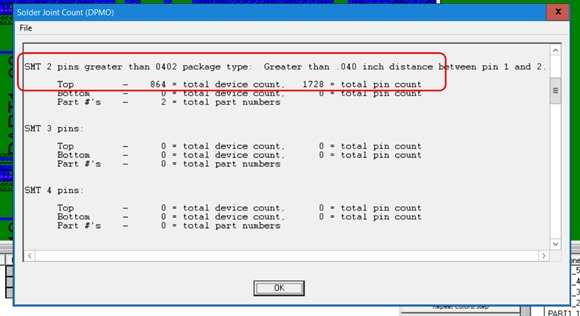
Also the Solder Joint Count (DPMO) report contains the total components packages and pins of each size.
Note: In addition to the method above the Unisoft software provides several methods to aid in quoting from gerber only files. Please contact Unisoft for details.