- Software Products
- Trial Software
- CAD Translation
- Testimonials
- Overview
- Pricing
- Knowledge Base
- Contact Us -
- Languages
The Assembly Process Document printing feature as been enhanced with two options - SINGLE PAGE EACH STEP or SEPARATE PAGES EACH STEP.
The procedure is PRINT ASSEMBLY SHEETS AND MATCHING LOAD LISTS FOR EACH PROCESS STEP: The assembly instructions for this PC Board are now complete. For this PC Board we have previously added 5 process STEPS. To Print Assembly Sheets and matching Assembly Load Lists for each process step in the window at the bottom of the display click the button PRINT ASSEMBLY DOCS.


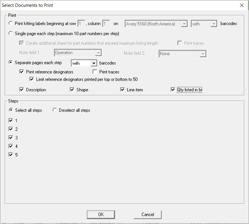
There are two options for printing Assembly Documents. The first option is SINGLE PAGE EACH STEP which results in a document that looks like the one below where each Step in the assembly process is printed on one sheet for each side of the PC Board assembly. Note in the figure below that the load list of the components to be inserted at that step are listed by part number at the top of the same sheet with the PC Board assembly under it and on the PC Board the components to be insert at this step are colored with matching colors to the load list above it.
To print this drawing below in the window above under PRINT select SINGLE PAGE EACH STEP and under STEPS click select ALL STEPS. Next click OK and select the printer or PDF file you wish to print to and Click OK and the document will be printed.
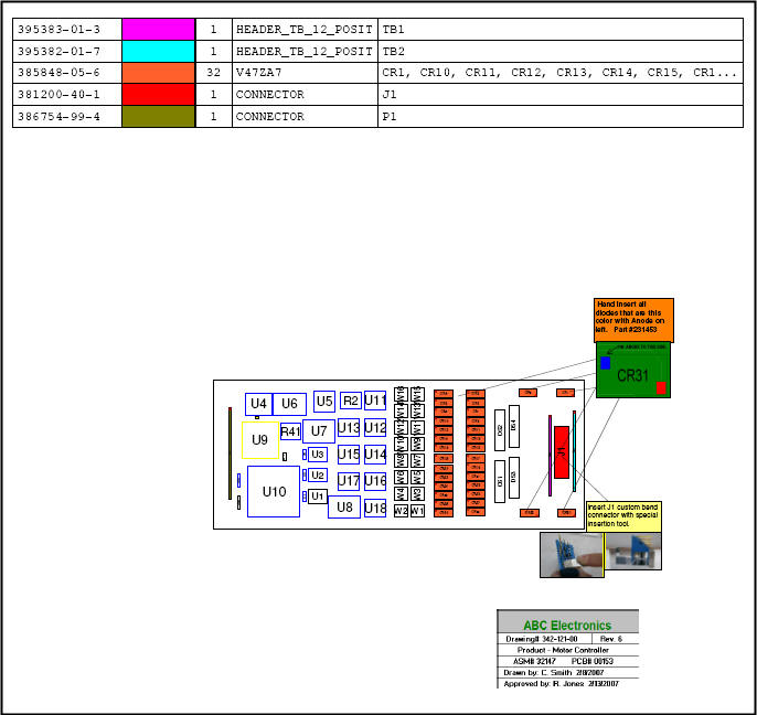
The second option for printing assembly documents is SEPARATE PAGES EACH STEP which results in a document that looks like the two figures below. Each Step in the assembly process is printed on two sheets for each side of the PC Board assembly. Note in the two figures below that the load list of the components to be inserted is on its own sheet and the PC Board assembly drawing is also on its own sheet. The load list and PC Board assembly drawings have color matching components to be inserted at this step.
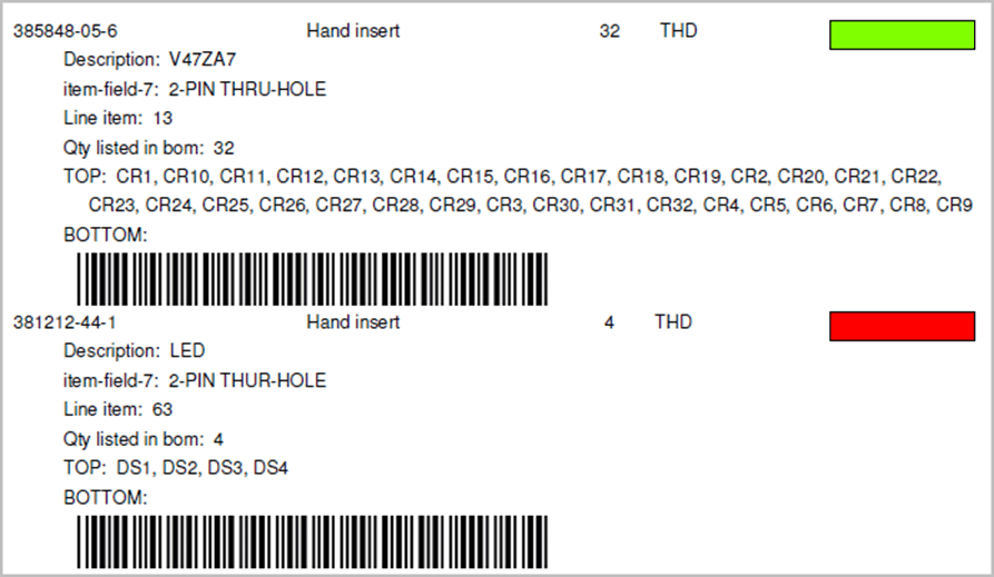
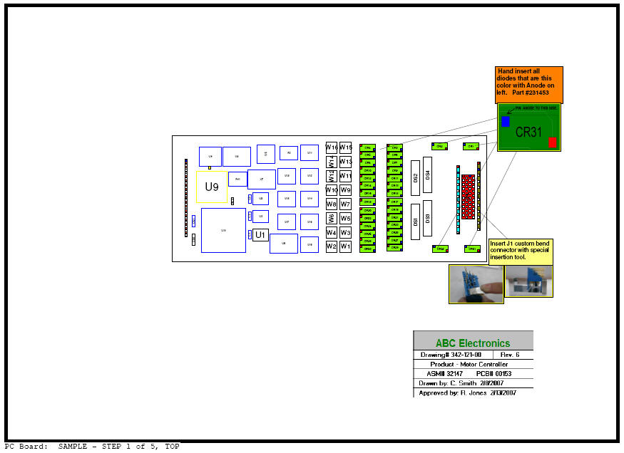
Note in the two drawings above that in the second drawing which is Assembly Sheet #1 of 5, CR1 to CR32 are colored green. Also printed are the 3 .F2P annotation overlays selected earlier for step 1 including "Hand insert all diodes that are this color", "insert J1 custom bend connector", and the legend box "ABC Electronics". In the first drawing which is the matching Assembly Load List Sheet #1 of 5, the third item is part number 385-848-05-6 which are components CR1-CR32 and for this item we have included automatically the part number, the operation text "hand insert diodes", the quantity of 32, the device type THD, the component part number color of green, and optionally additional Bill Of Material (BOM) information of tolerance/package/description, and top side reference designate or listings of CR1 through CR32.
To print the drawings above at the bottom center of the main display click the button PRINT ASSEMBLY DOCS and the window below appears. Under PRINT select SEPARATE PAGES EACH STEP and then put a check mark in all the 6 boxes located under SEPARATE PAGES EACH STEP. Next under STEPS click select ALL STEPS. Then click OK and select the printer or PDF file you wish to print to and Click OK and the document will be printed.
Related information:
Assembly documents - adding steps to part numbers
Assembly documents -
adding substeps to part numbers
Assembly documents -
manual "tutorial 1 - creating assembly/process sheets, annotation overlays and kitting labels"
Assembly documents -
kitting labels-1
kitting labels-2
kitting labels-3
Assembly documents - multiple pages per step
Assembly documents -
powerpoint and custom types
Assembly
documents - editing multiple assembly steps
Assembly documents - add pcb photos, etc. to the display background
Assembly documents -
for paperless assembly instructions when using the display only for slide
line pcb assembly, etc.
Barcodes on the display and assembly
documents