Use the Library to mark part numbers — for example, this can include
polarized components, "do not install" (DNI) parts, or other special
component operations.
A simple way to highlight part numbers and
their components that need to be inspected or assembled is to maintain a
Library containing your polarized or other special part numbers. You then
import that Library against the PCB that is being worked on. The
Operation field will be
automatically filled in with instructions on what to do. [Link
to library creation information.]
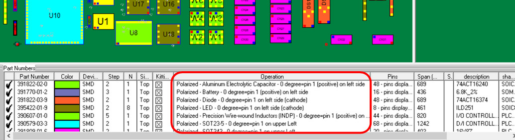
The library file might look like the following:
390222-07-1     Polarized - Diode - 0 degree=pin 1 on left side (cathode)
390579-03-3     Polarized - Capacitor - 0 degree=pin 1 (positive) on left side
395422-01-9     Polarized - LED - 0 degree=pin 1 on left side (cathode)
391822-02-0     Polarized - Aluminum Electrolytic Capacitor - 0 degree=pin 1 (positive) on left side
391822-03-9     Polarized - Diode - 0 degree=pin 1 on left side (cathode)
391818-06-6     Polarized - Tantalum Capacitors - 0 degree=pin 1 (positive) on left side
391809-01-6     Polarized - SOT343 - 0 degree=pin 1 on upper Left
390607-01-0     Polarized - Precision Wire-wound Inductors (INDP) - 0 degree=pin 1 (positive) on left side
390579-03-3     Polarized - SOT23-5 - 0 degree=pin 1 on upper Left
390222-06-2     Polarized - SOT23-3 - 0 degree=pin 1 on upper Left
385848-05-6     Polarized - Zener Diode - 0 degree=pin 1 on left side (cathode)
391770-01-2     Polarized - Battery - 0 degree=pin 1 (positive) on left side
Note: There can be as many
Library files as desired, and the example Library file above can contain an
unlimited number of part numbers. The part numbers listed above, such as
390222-07-1,
390579-03-3, etc., in this
example Library are in-house and not standardized part numbers.
Where
possible, it's best to use part numbers linked to a standard, such as the
Manufacturer Part Number (MPN). For example, these are MPNs:
CC0402CRNPO9BN2R2,
RC0201JR-0710RL,
DS520-30EAA02. The MPN is a
unique code used to identify different component parts, and it is
standardized and universally recognized.
After the Library is
imported, the Operation
field in the Smart Color
window at the bottom of the display will appear as shown below. The
Operation field will be filled in with instructions on what to do.
Components for each part number can be blinked and listed on the display and
acted on accordingly, or they can be color-coded, assigned a step number,
and printed.
This method within the Unisoft software allows users to selectively
turn component pins on or off by part number, making polarized and "Do Not
Install" (DNI) components stand out for inspection or assembly. Below is an
outline of how this feature operates, along
with other methods that can
achieve similar results.
Note:
When checking polarized parts, it is essential to ensure that their 0°
rotation has been set according to a recognized standard. The key constraint
in identifying polarized parts is that the part itself must have been
modeled based on a known specification.
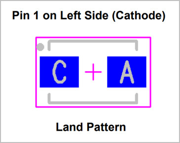
For example, the figure below
shows a diode component modeled according to the IPC-7351B Level A standard,
with 0° rotation defined as left-oriented, where the cathode (Pin 1) is on
the left. If the CAD file does not follow any known standard—such
as
when the PCB was designed using a smaller CAD system by a non-expert
designer, or if it is an older legacy design from a time when standards were
less stringent—then it's possible there may be no reliable reference point
for a known 0° rotation.
Although there has been progress in recent
years, a universal global standard for 0° component rotation does not yet
exist. However, the IPC-7351B Level A standard is currently the most widely
accepted, and it is the standard used by Unisoft software when
calculating 0° component rotation.
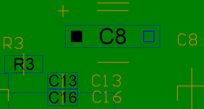
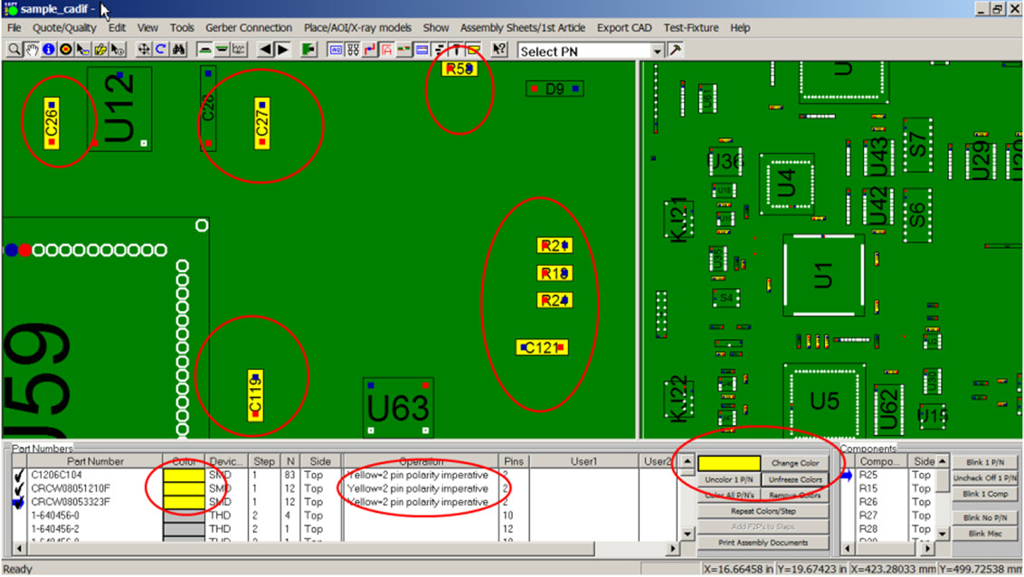
In the figure below, C8
is a polarized component, and the pins on that device have been left
ON to aid polarity
inspection and identification. The components
R3,
C13, and
C16 are non-polarized, and
the pins on those devices have been turned
OFF because they do not
require polarity inspection.
This feature—turning selective part numbers and their respective component pins on or off on the display—is useful in several areas of electronic manufacturing.
One example is the inspection of
polarized components. In this case, the user would direct the Unisoft
software to turn off all
pins on components that are not
polarized, allowing the polarized components to stand out and be easily
identified for inspection.
The inspection can then be performed directly
from the current display, or the components can be printed on an inspection
document.
Another example involves
selective components on the PC board that require hand assembly. In this
case, only those components would be displayed, with all others turned off,
simplifying the assembly process. The assembly can be performed either from
the current
display or by printing the components to an assembly
document.
There are two methods in the Unisoft
software for selectively turning component pins on or off by part number.
The first method is by selecting the EDIT STEP... window and toggling the PINS DISPLAYED OFF box accordingly.
The second method is by using a Library OPR file to specify particular part numbers for which the pins should be turned on or off.
The procedures for using these two mechanisms are outlined below. It is assumed that you have a working knowledge of how to use the Unisoft software. If you require training, please contact Unisoft directly
How to use the EDIT STEP method:
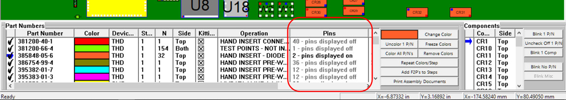
Open the SMART COLOR window at the bottom of the display, then double-click the part number you wish to edit.
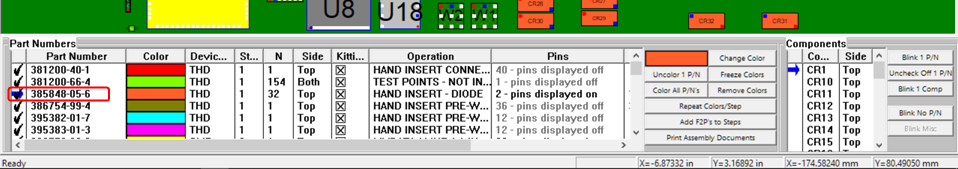
The EDIT STEP, OPERATION... window opens, and you can toggle the PINS DISPLAYED OFF feature box accordingly. By default, this box is unchecked, so initially, the pins for all part numbers and components will be displayed on the PCB.
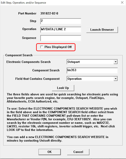
As the part numbers for component pins are turned on or off in the SMART COLOR window, the PINS field will reflect their status as either PINS DISPLAYED ON or PINS DISPLAYED OFF. If the state is PINS DISPLAYED OFF, it will appear dimmed in the SMART COLOR window.
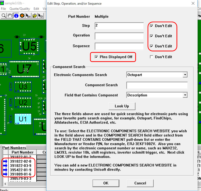
Note: Another feature of the SMART COLOR window is that you can select multiple part numbers to quickly toggle the pin states of those components OFF or ON. To do this in the Unisoft software, use the Ctrl key to select more than one part number individually, or select a range of part numbers using the Shift key.
How to use: In the SMART COLOR window, use the Ctrl key to select multiple part numbers one at a time, or use the Shift key to select a range of part numbers. Then, right-click on one of the selected part numbers, and the EDIT STEP, OPERATION... window will appear, allowing you to edit all selected part numbers at once.
In the figure below, in the lower left, four sequential part numbers outlined in red have been selected. To turn the pins OFF, the PINS DISPLAYED OFF box is checked. To prevent the editing of other fields, the three DON'T EDIT boxes are also checked. The result is that all the pins for all components of those four part numbers will be turned OFF on the display..
Use Example 1:
There are times when you will want to mark a whole group of part numbers to the
PINS DISPLAYED OFF state
quickly, and the feature described above will help you do that. For example,
usually polarized components are the minority of components on the PCB assembly
(PCBA), and since the initial default state for all component pins is
ON, the fastest way to set the
display up properly is to first turn all part numbers and their component pins
to OFF, and then either
singularly or via the OPR operations
file turn ON the minority part numbers you want displayed.
Use Example 2:
Most of the time, the information on which components to turn ON or OFF on the
display is either in the Bill of
Materials (BOM) or in an OPR
operation file, both of which can be quickly imported into the Unisoft
software. You can simply sort on any field in the
SMART COLOR window and then
group part numbers as either ON
or OFF on the display as
desired. For example, if the BOM or OPR file indicates which part numbers are
polarized, then those part number component pins can be turned
ON on the display for easy
inspection.
How to use the library .OPR file method:
Create an
.OPR library file with
the part numbers you wish to edit.
To
automatically turn OFF
all the component pins for all the components in a part number, use the
following command in the second field:
= $PinsDisplayedOff
To automatically turn ON
all the component pins for all the components in a part number, use the
following command in the second field:
= $PinsDisplayedOn
Example of an OPR library file:
385848-05-6    $PinsDisplayedOff
391781-01-4    $PinsDisplayedOff
381212-44-1    $PinsDisplayedOff
390607-01-0    $PinsDisplayedOn
390579-03-3    $PinsDisplayedOn
395422-01-9    $PinsDisplayedOn
The default condition is that, initially, for all part numbers and all components, the pins are displayed on the PCB.
Next, import the OPR library file by clicking the FILE menu, then selecting IMPORT LIBRARY (.OPR)..., choosing the library you created, and clicking OPEN. The result is that the pins for the components on the PCB assembly (PCBA) will be turned OFF or ON accordingly.
In the SMART COLOR window, the PINS field will represent them as either PINS DISPLAYED ON or PINS DISPLAYED OFF. If the state is PINS DISPLAYED OFF, it will appear dimmed in the SMART COLOR window.
A simple example is to create a library with your polarized
components in it, import that library, and then turn the pins OFF for
all components that do not have a polarized notation in the
Operation field. As a
result, the components that remain
with pins ON in the display will
be the polarized components to be inspected. [Link
to library creation information.]
The library file might look like the following:
390222-07-1     Polarized - Diode - 0 degree=pin 1 on left side (cathode)
390579-03-3     Polarized - Capacitor - 0 degree=pin 1 (positive) on left side
395422-01-9     Polarized - LED - 0 degree=pin 1 on left side (cathode)
391822-02-0     Polarized - Aluminum Electrolytic Capacitor - 0 degree=pin 1 (positive) on left side
391822-03-9     Polarized - Diode - 0 degree=pin 1 on left side (cathode)
391818-06-6     Polarized - Tantalum Capacitors - 0 degree=pin 1 (positive) on left side
391809-01-6     Polarized - SOT343 - 0 degree=pin 1 on upper Left
390607-01-0     Polarized - Precision Wire-wound Inductors (INDP) - 0 degree=pin 1 (positive) on left side
390579-03-3     Polarized - SOT23-5 - 0 degree=pin 1 on upper Left
390222-06-2     Polarized - SOT23-3 - 0 degree=pin 1 on upper Left
385848-05-6     Polarized - Zener Diode - 0 degree=pin 1 on left side (cathode)
391770-01-2     Polarized - Battery - 0 degree=pin 1 (positive) on left side
Additional method: Use color-coding to identify component
groups (e.g., assembly step groups,
polarized components) in order
to aid assembly, rework, and inspection
For coloring components to assist with assembly and
inspection—such as identifying polarized components—you can assign a
single color to all part numbers that are polarized. For example, in the
example below, we have used yellow. You can also optionally add a note
and
associate it with a step number. In the example, we used the
note "Yellow = 2 pin polarity
imperative" and placed the three part numbers colored yellow in
step #1. Note:
assigning a step number is optional.For coloring components for assembly
aids inspection aids etc.
To apply the color:
Click on the part number you wish to color in the SMART COLOR window at the bottom.
Click the "Color 1 P/N" button.
Then click the "Change Color" button and select the color you want.
Once you have colored all the desired part numbers:
Click "Freeze Color" to freeze the colors on the display.
If desired, you can print these out. If a unique step number is used, all yellow-colored components will print on a single sheet. Alternatively, if you do not wish to print, you can simply use the "Blink 1 P/N" button on the screen to visually highlight part numbers and aid assembly and inspection.
Optionally, you can also have
the library indicate which parts need special attention because they are
polarized. This way, when you have a new design, you can simply import
the library, and it will automatically tag the part numbers on the
assembly.
Then, it’s easy to color them accordingly.
Here is an example of the
library: [Link to library
creation information.]
CRCW08051210F
Yellow=2 pin polarity imperative
CRCW080553323F
Yellow=2 pin polarity imperative
Alternatively, if you already
have this type of information—or any information—associated with the
part number in your MRP or ERP system, you can simply export it and
import it into Unisoft
for your PCB through the library.
Below are a few additional options for making polarized
components stand out for inspection or assembly; some of these have been
outlined above. We are
assuming you are an experienced user of the Unisoft
software. Please contact us for training.
OPTION: In the SMART COLOR window, you can assign a step number to the polarized components and print out a single sheet for that step number, which will contain only the polarized components in color.
OPTION: You can also create
a process step number—similar to the option above—for only polarized parts,
and print out a graphic section of only the PCB assembly (PCBA). Then, place
it as an annotation overlay graphic on top of the assembly
and bring it
to the forefront. The result is that only the polarized parts will be
visible on the display.
OPTION: Apply solid colors to only the polarized components on the display using the SMART COLOR window by using the COLOR 1 P/N feature. If you want them to all be the same color or a unique color, also use the CHANGE COLOR feature.
OPTION: If you have a PCB
assembly (PCBA) that consists mostly of polarized components and only a few
non-polarized components—for example, R1, R2, and U1—it may be quickest to
change the color of the pins and, if desired, the component bodies of these
non-polarized components to the same color as the background. At that point,
the non-polarized components will fade into the background and become
essentially invisible, while the colored polarized components will stand out
on the display. You can then use the display or a printout of the display
for inspection, assembly, etc.
More information:
For questions and training, please contact Unisoft.