Related information:
Quoting by span: Assembly Cost or Time by Component Count Span Report for
Quoting
Quoting by p/n:
Assembly or Parts Cost or Time by Part Number Report for Quoting
Quoting from gerbers: Quoting Using Only Gerber
Files
Cycle Times
There are a few options for calculating the Solder Joint Count using the Unisoft software. Two methods to determine the Solder Joint Count totals are outline below.
Solder Joint Count totals are used by contract and OEM electronic manufactures for quoting jobs and quality reports such as Defect Per Million Operations (DPMO), etc. Contact Unisoft for details.
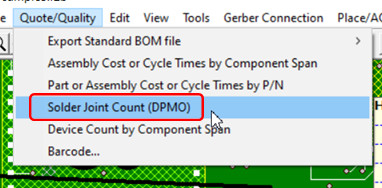
Create a report of the total Solder Joint Count from the SOLDER JOINT COUNT (DPMO) menu.
To use: To generate the Solder Joint Report open the desired PC Board with the Unisoft software. Next click QUOTE/QUALITY from the main menu then click SOLDER JOINT COUNT (DPMO) and the report appears.
This report contains the total solder joints for the PC Board broken down by SMT and Thru Hole components, part numbers and package sizes.
Example report:
Report type: Solder joint count totals.

PC Board: Sample
Date: 6-12-21

Total Solder Joints = 1104
Total SMT Solder Joints = 598
Total Thru Hole Solder Joints = 506

----

SMT 2 pins greater than 0402 package type: Greater than .040 inch distance between pin 1 and 2.
Top - 4 = total device count, 8 = total pin count
Bottom - 78 = total device count, 156 = total pin count
Part #'s - 8 = total part numbers

SMT 8 pins and greater and greater than 30 mils pin spacing:
Top - 17 = total device count, 290 = total pin count
Bottom - 0 = total device count, 0 = total pin count
Part #'s - 8 = total part numbers
BGA's - 0 = included in above count.

Thru-hole 2 pins:
Top - 34 = total device count, 68 = total pin count
Bottom - 0 = total device count, 0 = total pin count
Part #'s - 3 = total part numbers

Thru-hole 8 pins and greater:
Top - 24 = total device count, 284 = total pin count
Bottom - 0 = total device count, 0 = total pin count
Part #'s - 6 = total part numbers
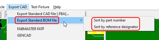
This method exports a standardized BOM by either part number or reference designator.
To use: To export a standardized BOM report file by either part number or reference designator open the desired PC Board with the Unisoft software. Next click EXPORT CAD from the main menu and then click EXPORT STANDARD BOM FILE. Then select either SORT BY PART NUMBER or SORT BY REFERENCE DESIGNATOR and that report is created.
The file created is a tab-delimited ASCII file that can be imported into Microsoft Excel, etc. and the data fields can be sorted as desired.
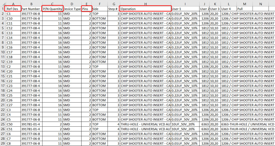
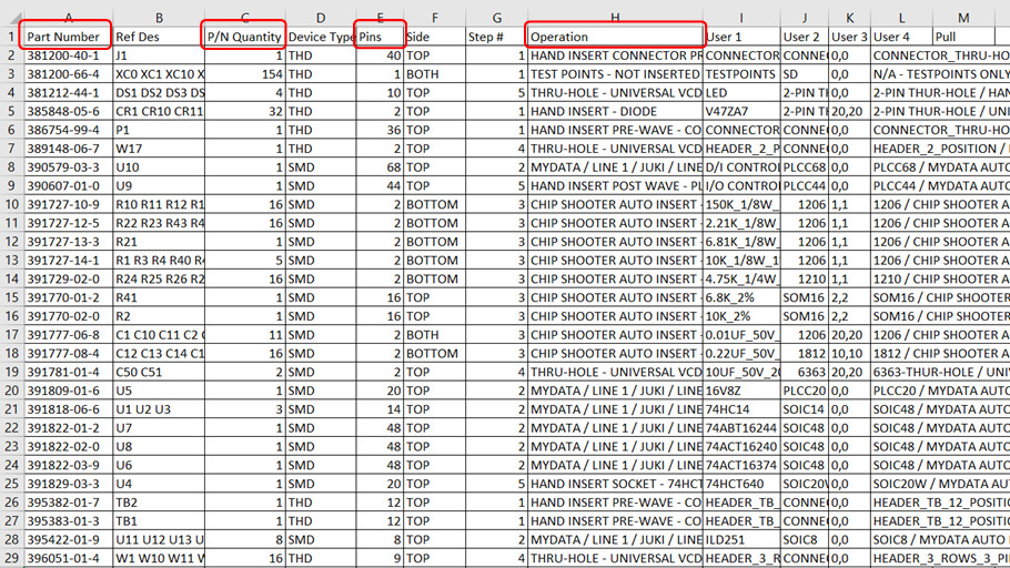
In the part number or reference designator BOM export report the field PINS is for the number of pins (solder joints) for the component and the field P/N QUANTITY is the quantity of the components with that part number.
For the Solder Joint Count multiply the PINS field by the P/N QUANTITY field.
To breakdown the Solder Joint Count further sort on the other fields in the report. For example sorting on the field SIDE will provide the Solder Joint Count for either the top or bottom side of the PCB. Or sorting by the OPERATION field could give the total Solder Joint Count for example for HAND INSERTED components, etc.
Example report by Part Number:
Example report by Reference Designator: