Get Your Free Trial Software
Fully functional · No credit card required
Fully functional trial licenses,
available at no charge, are normally provided for approximately one month to
allow you to try out the software. Let us know if you're interested.

Click here for software download & more information!

ProntoVIEW-MARKUP is software used by PCB
assembly (PCBA) electronic manufacturers for detailed viewing of PC board
assemblies and for creating documents and other items needed throughout the PCB
assembly process.
The software improves efficiency, communication, and
reduces errors across the production floor. It has over 100 features and is used
daily by multiple departments, including management, assembly, inspection,
design, test, troubleshooting technicians, and other personnel.
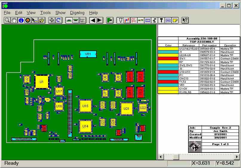
ProntoVIEW-MARKUP creates assembly instructions using unique colors for
each part number and each step in the assembly process, and it generates
matching kitting labels. It can locate any component, pin, or part number,
find shorts between traces, displays netlists, and provide a paperless,
hyperlinked schematic tied directly to the assembly. It also allows users to
add annotation notes and graphics.
The software supports fast PC
board first article inspection as well as general inspection. It can
generate reports with device and package type counts, along with quotation
and cost estimation data.
With a current license, you can distribute the included Unisoft PC board
viewer to your production floor, vendors, and customers to support assembly,
first article inspection, general inspection, repair/rework, and technician
debugging, improving overall communication.
If needed, ProntoVIEW-MARKUP
can also be controlled remotely from your application or equipment using the
supplied external API programming interface.
To start or schedule a meeting
Click Here or email us (enable JavaScript for our email addresscad-to-cad.php) or call us (enable JavaScript for our phone number).
In our meeting, we can follow any direction you prefer, for instance:
-- Talk about your requirements, software inquiries, and other concerns.
-- Software demonstrations & training. We have the option to process one of your PC Boards or demonstrate the software using our own data files.
-- Provide you with a fully functional trial version of the software license.
-- etc.
Additional Benefits of using ProntoVIEW-MARKUP for overall Shop Floor PCB
Assembly Operations
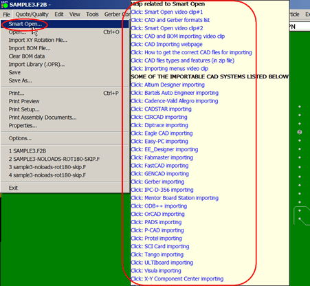
ProntoVIEW-MARKUP
automatically processes the wide range of file formats that make up CAD
files, XY rotation data, Gerber-only data, and BOM files. These can combine
in hundreds of different ways for each unique PCB design, and Unisoft brings
all of that together to generate complete data to be used for overall PCB
Shop Floor Operations.
Unisoft has been doing this for over 40 years
and has thousands of customers, so the depth of our importers is unmatched.
That’s usually not the case with the importers that come from other software
sources. It’s just a different standard. Our standard is simple: we read
everything in—modern and legacy PCB designs—and we do it correctly, every
time, no exceptions.
The whole issue of dealing with multiple file
formats from customers—whether they’re electronic contract manufacturers or
large OEMs—is handled and solved by Unisoft.
This includes
extracting reference designators, rotations, part numbers, package shapes,
component pins, netlist data, trace runs, and more. All of that data is
available inside ProntoVIEW-MARKUP and is used to support a wide range of
shop floor operations across the production floor, including assembly,
inspection, and other related processes.
For example,
ProntoVIEW-MARKUP can be used to create assembly process documents, generate
kitting labels, perform first article inspection, produce assembly and part
cost reports, and generate solder joint count reports (DPMO – Defects Per
Million Operations). It also supports assembly, rework, repair, and
technician troubleshooting, along with hundreds of other functions—all from
a single software system.
ProntoVIEW-MARKUP can be upgraded to
program Assembly Pick & Place, AOI, Test & Selective Soldering Machines. The
ProntoVIEW-MARKUP prepared data can be used inside this production floor
machine programming environment. In practice, this means our software
handles the CAD translation and data preparation, while the machine software
handles the final production floor machine-specific program generation. This
combination typically simplifies the programming workflow and reduces the
amount of manual work normally required when preparing machine programs.
If you have multiple Assembly Pick & Place machine models from different
vendors then those can all be programmed at the same time using Unisoft. The
same applies to AOI inspection machines, ATE test equipment, and selective
soldering machines. All of these can be handled and programmed from the same
software environment.
Manufacturing Execution System (MES) software
is also available and is used on the shop floor to track and control PCB
production in real time.
Some features
of
ProntoVIEW-MARKUP:
Other features in the Unisoft software suite:

The software has HELP for most menu items by hovering over the menu item for a second then click any of the videos, manual or website links to learn about the software.
VIDEO: Click the video above for product overview.
Please double check that your email address is correct.
Email addresses are kept private.
The software download link, more information and periodic updates will be sent to this address.
Optionally to receive your software call us (enable JavaScript for our phone number).

The basic features of ProntoVIEW-MARKUP provides the detailed viewing of PC board assemblies and the creation of documents, etc. required throughout the PCB assembly ( PCBA ) process. The software increases efficiency, communications and reduces errors across the production floor. With over 100 features aids every department every day on the shop floor of PCB assembly ( PCBA ) manufacturers where it is used by management, assembly, inspection, design, Test, troubleshooting technicians and other personnel.
The information and figures that follow outline a few of the features of ProntoVIEW-MARKUP (listed above).
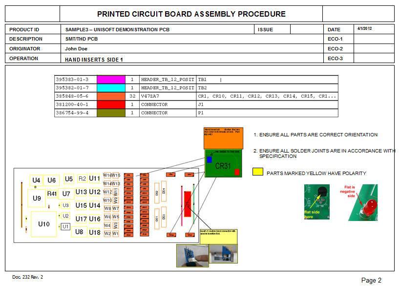
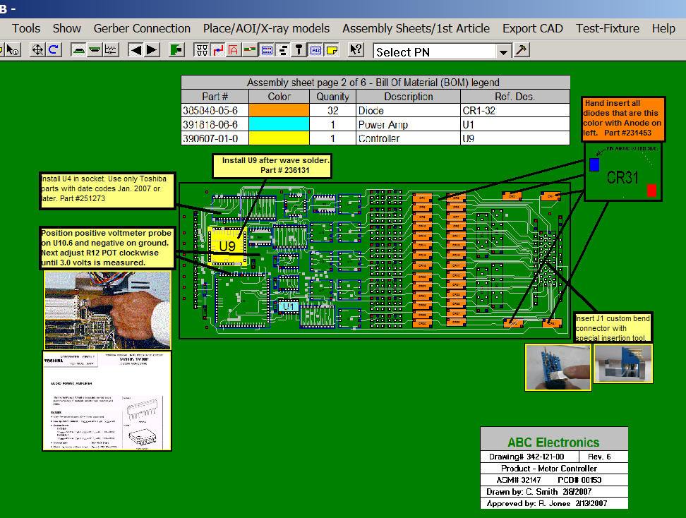
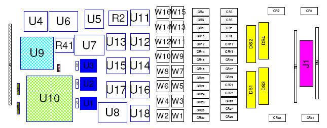
The Unisoft software allows you to quickly create matching assembly lists and assembly drawing sheets for each step in the assembly process. Part numbers are automatically assigned to the assembly step you wish (for example: Step 1 for Hand Inserts, Step 2 Chip Shooter components, etc). The part numbers are then automatically uniquely colored. If needed, overlay annotation notes can be added to each step. Next for each step matching assembly lists and assembly drawings are created. These drawings can either be printed or save to a file (PDF Adobe, etc.) or displayed on the screen.
Download a sample of process and assembly sheet documentation created by this software.


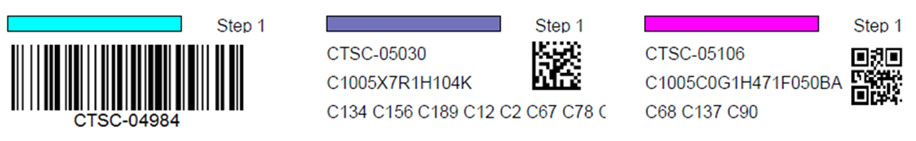
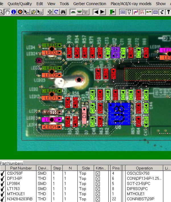
The Unisoft software allows you to quickly create Kitting Labels with barcodes for fast and accurate electronic component kitting. Quickly select the component part numbers for which you wish kitting labels created. Each label contains the part number, unique part number color, step number, p/n description, reference designator, etc. Fast and easy electronic kitting labels for kitting work orders.
Barcodes of various types can be printed on the kitting labels and shown on the display for quick kitting,
fast assembly machine feeder loading, verification, inspection, etc.: 2d-qr code, 2d-data matrix, etc.

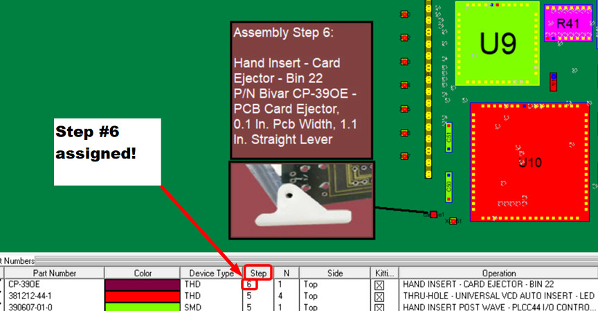
This feature of the Unisoft
software allows you to add parts, processes, and other items that are not
part of the actual electrical circuitry on the PC board. These elements can
then be assigned to individual assembly process steps and treated like any
other step within the Unisoft software. You can add just a few additional
steps or, if desired, define the entire PCB assembly process—from the
pre-assembly stage to the main assembly stage, and continuing through the
point at which the fully assembled PCB is integrated into its subassembly.
For more information about this feature,
please click here.
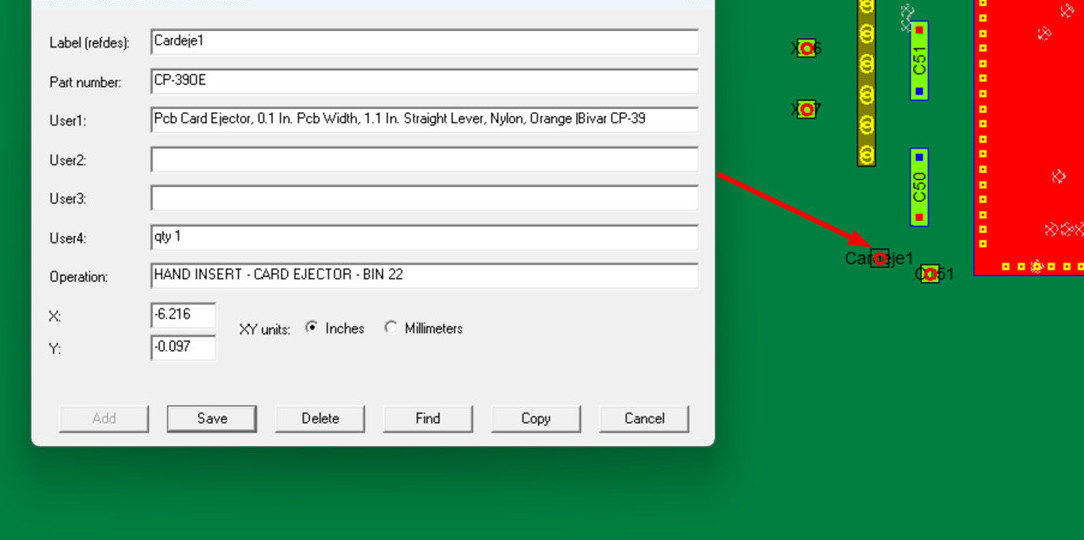
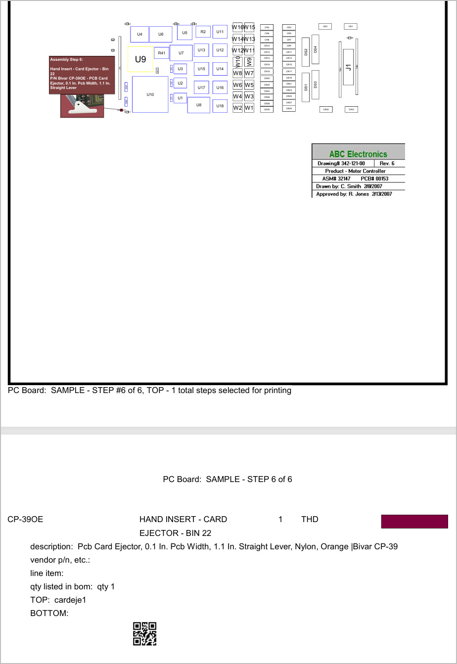
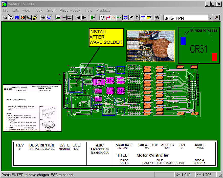
For instance, if you need to add a PC board
card ejector by hand to the assembly process, you can enter that item along
with corresponding annotation text, notes, and pictures. You can then assign
it to a specific assembly step and treat it just like any other process step
in the Unisoft software. In the figures above, we’ve added a non-electrical
part—specifically, a card ejector—labeled "Cardeje1" as its reference
designator, with a part number of CP-390E, onto the PCB and created an
additional step—Step 6—to manually insert that part onto the PCB. Next, we
create and assigned one annotation containing text and another containing a
picture to step 6.
Then, in the example shown in the figure below, we
use the standard Unisoft “Print Assembly Document” feature to print Step
Number 6. If you choose not to print, the operator can simply work from the
on-screen display and complete the assembly—just like with any other step
operation.
Below are some examples of
non-electrical parts and processes that can be involved in completing a PCB
assembly. You may also create as many steps as desired—for example, you can
extend your steps to include pre-assembly and post-assembly processes. For
more details,
please click here.
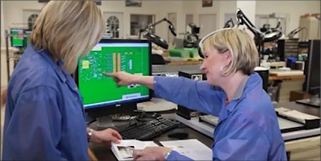
ASSEMBLY:
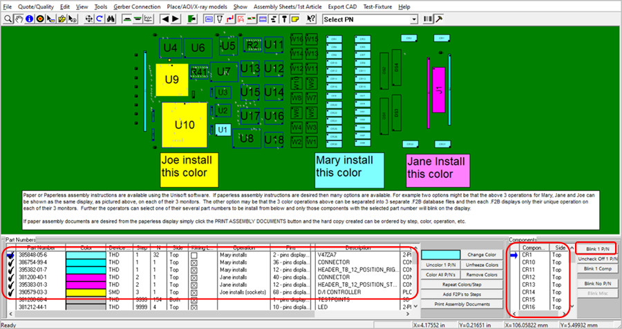
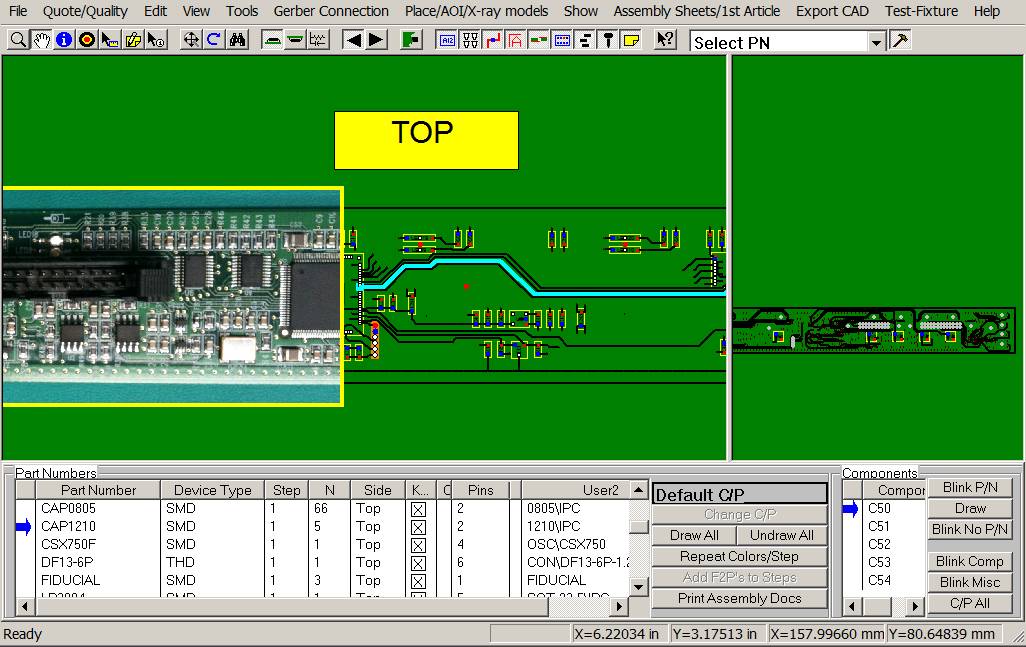
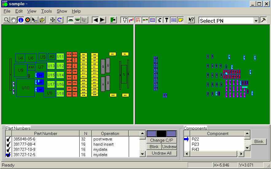
Paper or Paperless assembly instructions are available using the Unisoft software. If paperless assembly instructions are desired then many options are available. For example two options might be that the below 3 operations for Mary, Jane and Joe can be shown as the same display, as pictured above, on each of their 3 monitors. The other option may be that the 3 color operations above can be separated into 3 separate .F2B database files and then each .F2B displays only their unique operation on each of their 3 monitors.
Further the operators can select one of their several part numbers to be install from below and only those components with the selected part number will blink on the display.
If paper assembly documents are desired from the paperless display simply click the PRINT ASSEMBLY DOCUMENTS button and the hard copy created can be ordered by step, color, operation, etc.
Import your PC Board into the Unisoft manufacturing software and you instantly receive a report containing component counts for top and bottom of the PC Board broken down by SMT, Fine pitch, BGA's, Thru-hole, etc. with the cost for each group. You can create as many PCB assembly ( PCBA ) Cost templates as you wish, for example one each for either a Low, Medium or High volume build. This is a great quoting time saver for Contract and OEM manufacturers.


Example of a few lines of a report follows:
PC Board:   123-456
Date:       1-22-2013

    Base 1st Unit Assembly Build Rate (Includes P/N Setup Rate) = 219.18

    Each Unit Assembly Build Rate (Excludes P/N Setup Rate)     = 74.18

    Total Part Number Setup Rate                                = 145.00
________

SMT 2 pins greater than 0402 package type:  Greater than .040 inch distance between pin 1 and 2.
    Top      -  4 = total device count, 8 = total pin count
    Bottom   -  78 = total device count, 156 = total pin count
    Part #'s -  8 = total part numbers
    Base Rate:  49.84 = (0.12 * device count) + (5.00 * part #'s)

SMT 8 pins and greater and 30 mils or less pin spacing (fine pitch):
    Top      -  3 = total device count, 144 = total pin count
    Bottom   -  0 = total device count, 0 = total pin count
    Part #'s -  3 = total part numbers
    BGA's    -  0 = included in above count.
    Base Rate:  15.48 = (0.16 * device count) + (5.00 * part #'s) + (0.75 * BGA count)
Instantly create a component part cost report. This report is used by Contract and OEM manufacturers to quickly estimate component parts costs. The report contains the total component part cost for the PC Board and breakdown by part number.
Report type: Parts count with quotation and cost estimation.

PC Board: Controller
Date: 1-12-09
Total parts cost = $43.31
____
| 381200-40-1 | 1 | $0.23 | $0.23 |
| 381212-44-1 | 4 | $0.07 | $0.28 |
| 385848-05-6 | 32 | $0.45 | $14.40 |
| 386754-99-4 | 1 | $0.16 | $0.16 |
| 389148-06-7 | 1 | $0.06 | $0.06 |
| 390579-03-3 | 1 | $0.80 | $0.80 |
| 390607-01-0 | 1 | $0.65 | $0.65 |
| 391727-10-9 | 16 | $0.04 | $0.56 |
| 391727-12-5 | 16 | $0.04 | $0.64 |
Instantly create a report of the total solder joint count for Defect Per Million Operations (DPMO). This report is used by Contract and OEM manufacturers for quality tracking. The report contains the total solder joints for the PC Board broken down by SMT and Thru Hole and part number.
Report type: Solder joint count with quotation and DPMO estimation.

PC Board: Controller
Date: 1-12-09

Total Solder Joints = 1104
Total SMT Solder Joints = 598
Total Thru Hole Solder Joints = 506
____

SMT 2 pins greater than 0402 package type: Greater than .040 inch distance between pin 1 and 2.
    Top - 4 = total device count, 8 = total pin count
    Bottom - 78 = total device count, 156 = total pin count
    Part #'s - 8 = total part numbers

SMT 8 pins and greater and greater than 30 mils pin spacing:
    Top - 17 = total device count, 290 = total pin count
    Bottom - 0 = total device count, 0 = total pin count
    Part #'s - 8 = total part numbers
    BGA's - 0 = included in above count.

Thru-hole 2 pins:
    Top - 34 = total device count, 68 = total pin count
    Bottom - 0 = total device count, 0 = total pin count
    Part #'s - 3 = total part numbers

Thru-hole 8 pins and greater:
    Top - 24 = total device count, 284 = total pin count
    Bottom - 0 = total device count, 0 = total pin count
    Part #'s - 6 = total part numbers
The Electronic Components Search feature helps you find information such as cost, availability, part shape, electrical specifications, etc. Provides fast searching for electronic parts using your favorite parts search engine for example Octopart, FindChips, Alldatasheets, ECIA Authorized, etc.
Search for electronic parts using the Manufacturer or Vendor P/N for example ERJ-3EKF1002V. Also search by the electronic component number or name such as MAX232, LM393, resistor 10k, shift registers, inverter schmitt trigger, etc.


All types of Bill of Material (BOM) formats can be imported into the Unisoft software and then exported to normalized standard BOM formats that can then be utilized by your other manufacturing software systems such as Part Sourcing, MRP, ERP, etc.


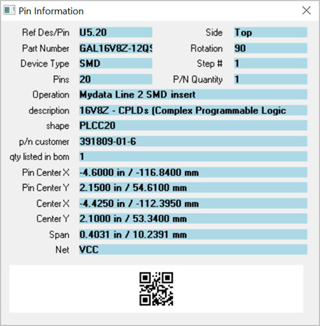
Easier drill down to component pins, trace runs and schematic. Display NETLISTS quickly using the "NET INFORMATION" window that displays the NET NAME of the selected component and pin and all the other pins on the net. The trace run of the selected net is highlighted and all pins on the net blink. If the schematic view is displayed then the net chosen is shown. The user can then select any one of the other pins on the net in the NET INFORMATION box. The result is the NET INFORMATION window will update to the new selected pin and the selected trace highlighted will update also. If the schematic view is displayed then that view will refresh too.


Find shorts between traces, netlists, netnames, component information, etc.
The Unisoft software outputs a single board file of the PCB assembly ( PCBA ) that is compatible with the included PCB assembly ( PCBA ) viewer. Customers with a current license can distribute the PCB assembly ( PCBA ) viewer and the Unisoft PCB assembly ( PCBA ) board file to your production floor, other divisions, vendors, customers, etc. to aid assembly, first article inspection, general inspection, repair/rework, technician debug, for enhanced communications, etc.

Unisoft
provides alternative solutions for organizations evaluating products such as
Fab3000, ScanCAD, Aegis CircuitCAM, Siemens Unicam, Aegis FactoryLogix,
Aster Technologies Testway Siemens, CAM350, and ViewMate. All referenced
product names, company names, and trademarks are the property of their
respective owners and are used strictly for identification and comparison
purposes. Unisoft is an independent company and has no affiliation,
sponsorship, endorsement, or other relationship with these trademark owners
or their products.
Unisoft: Manufacturing software since 1985